Source 3000 Self-Contained Pressure Source Console Operation and Maintenance Manual 65546
Source 3000 Operation and Maintenance Manual
Contents About This Manual ................................................................................................................................... 1 1.0 Introduction.................................................................................................................................. 1 2.0 Operation...................................................................................................................................... 3 2.1 Pressure Cylinder Filling . . . . . . . . . . .
ii Source 3000 Operation and Maintenance Manual
About This Manual The Source 3000 is a portable, self-contained pneumatic pressure console with precision vernier. A rugged, compact instrument manufactured by Condec, designed to provide ease of operation when used in conjunction with multiple manufacturers electronic calibrators, for the calibration of a wide variety of pressure sensing and measuring devices.
The heart of the Source 3000 are the two micro-metering valves and the vernier provided for control of the internal nitrogen source. Overpressure protection is provided by a fully adjustable pressure regulator which is manually set for each new device being tested. The Source 3000 is designed for compatibility with all major manufacturer’s electronic calibration equipment. The following schematic provides an overview of the Source 3000’s function.
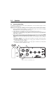
2.0 2.1 Operation Pressure Cylinder Filling To initially fill or refill the internal pressure cylinder (3000 PSI max.) of the Source 3000, see Figure 2-1 below and proceed as described below. NOTE: The pressure cylinder used as the filling source must be regulated to provide a maximum output of 3049 PSIG. 1. Rotate the PRESSURE LIMIT CONTROL (1) counter-clockwise until it stops. Close the COARSE ADJUSTMENT valve (2) by rotating clockwise until it stops. 2.
2.2 Initial Setup To prepare for actual calibration usage, see Figure 2-2 below and proceed as follows: 1. Check that the COARSE ADJUSTMENT valve (1) is closed (rotate clockwise until it stops) and that the vent valve (2) is open (two turns counter-clockwise from its stop). 2.
3.0 3.
3.2.3 Installing New Nitrogen Cylinder Assembly (PN 65622) Tools required: 7/16" wrench Phillips screwdriver 1-1/8" wrench 3/8" wrench 4" of 1/4"-wide Teflon tape (PN 60575) 4" of 1/2"-wide Teflon tape (PN 60911) tube of fluorinated Krytox grease (PN 55593) bottle of liquid leak gas detector (PN 64781) 1. Install the Teflon O-ring (PN 59217), fitting (PN 59287), and elbow (PN 59874) on the new cylinder (PN 65458) and tighten until snug.
1. Secure the manifold by its center portion, in a bench vise, with the valve knobs pointing upward. 2. Using the .061" hex wrench, loosen and remove the knob inserts (4) from the pressure and vent valve stems. 3. Loosen the 3/4" locknuts (1) on the pressure and vent valve threaded needle housings (10). 4. Using the needle housing socket (65580) and torque wrench, loosen and remove the needle/housing assembly (10, 1). 5.
3.2.7 ORION 2C Manifold, Vernier Control Reassembly Tools required: tube fluorinated Krytox grease (PN 55593) 1-1/4" wrench screwdriver (flat-blade) socket wrench isolation valve socket (PN 59793) female socket (PN 65581) 1. Coat all new O-rings with fluorinated Krytox grease before installing. 2. Install the small O-ring (27) into the end cap inner groove. 3. Add mylar washers (41) or (42) to each side of shaft (14). NOTE: Part number and quantity will vary.
9. Mount the manifold body (16) in a vise. For the pressure and vent valves only, torque the needle/housing assembly to 325 in-lb. using the needle housing socket (PN 65580). 10. Install the housing lock nuts (1) onto the housing (10) and tighten until snug with the 3/4" socket. 11. Install the knob insert (4) over the needle shaft, align the set screws with the indents and tighten with the .061" hex wrench. 12.
knob clockwise until the isolation valve is slightly snug. To avoid damage to the seat, do not use excessive torque! 13. Remove the knob. Align the two set screws with the indentations on the knob insert. Install the knob on the knob insert while engaging the knob gear with the isolation valve gear. 14. Tighten the two set screws with the .061" hex wrench. The PRESSURE valve is now adjusted. 15. To adjust the VENT valve, follow steps 3 and 4. 16.
3.2.13 Panel Gage Removal Tools required: Phillips screwdriver 7/16" wrench 9/16 " wrench 1. Vent any remaining gas from the nitrogen cylinder to atmosphere. 2. Remove front panel from its enclosure as described in Section 3.2.1 on page 5, and carefully place on a bench top. 3. Disconnect the tubing section that connects to the gage fitting. 4. Loosen the two thumb-nuts that hold the gage mounting U-clamp. 5.
3.2.16 Port 1, Port 2 and Fill Port Filter (PN 54188) The port filter is a sintered element filter which is easily removed for inspection and cleaning. Tools required: Phillips screwdriver 7/16" wrench 9/16 " wrench A/R solvent (de-natured alcohol) bottle of liquid leak gas detector (PN 64781) Port 1 or Port 2 Filter Removal 1. Vent any remaining gas from the nitrogen cylinder to atmosphere. 2. Remove front panel from its enclosure as described in Section 3.2.
4. Remove the male reducing adapter/run tee assembly from the check valve. 5. Remove the check valve from the female elbow fitting. Remove any remnants of Teflon tape from the pipe threads. Note direction of flow arrow. Check Valve Disassembly 1. Remove lock screw from the inlet end (tail of flow arrow) using a 5/32" hex wrench. 2. Force insert out by pushing against poppet with a blunt pin inserted into outlet. Remove poppet and spring and clean in solvent.
Ref Number PN 20 56784 Locknut,9/16-18UNF-3A, SST 1 21 59845 Plug,Expansion , .1562 +.0000/-.
38 16 10 1 2 33 25/2X 34 23/2X 4 D C 7 32 24/3X 9 3 28 31 15 27 35/2X 20 30 8 12 41 OR B 5 42 17 7 21/14 11 14 A 27 9 25/2X 28 26/2X 31 41 OR 36 42 27 29 30 8 13 19 18 6 Figure 3-3.
4.0 Specifications Pressure Specifications: Pressure Hose Fittings: Pressure range: Based on vendor’s electronics Available pressure calibrations: Gage only, absolute only, or gage and absolute Overall accuracy: Based on vendor’s electronics Operating Temperature:+40° to +110°F (+4.4° to +43.3° C) Storage Temperature: 0° to +185° F (–17.8° to +85°C) Pressure Media: Dry gaseous nitrogen, standard Quantity Supplied: Style: Internal Pressure Cylinder: Capacity: 15.
Source 3000 Warranty and Return Policy If possible, please save original packing material which is specifically designed for the unit. Should it be necessary to ship the unit back to the factory, a suitable shipping container must be used along with sufficient packing material. Do not put a shipping label on the unit as a "suitable shipping container." Some units have been severely damaged this way. This is a delicate, precision instrument.
Source 3000 Return Material Authorization Form The repair lab is also equipped to do calibrations on our calibrators and pressure standards. Calibrations include a certification and are traceable to N.I.S.T.