
User Manual

3
.
OUT 2 COM OUT 2 COM TB3-6
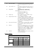
5. LOGIC OUTPUT:
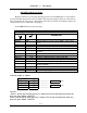
The logic output is available on the 1/0 terminal block TB2 on the CPU assembly.
Trip 1: TB2-2
Trip 2: TB2-3
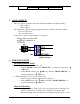
The 1/0 must be selected by jumper plugs P4 and P5 for OUT on the CPU assembly.
P4 set for OUT at S4
P5 set for OUT at S5
A trip “ON” condition “relay energized” is a logic “0”
6. TRIP POINT SETUP
SELECTING TRIP PT SETUP:
1. MAIN SETUP: Close rocker switch 1 only.
• Press the ⇓⇓
⇓⇓
“NO” key until the "SETUP 1/0 ?" is selected and then press ⇑⇑
⇑⇑
“YES” key.
• In the SETUP 1/0 press the ⇓⇓
⇓⇓
”NO” key until the "SETUP TRIP PT ?" is
selected and then press ⇑⇑
⇑⇑
“YES” key.
2. SET-UP 1/0 (direct): Close rocker switch 3 only.
• Indicator is placed directly into the 1/0 set up mode.
• In the SETUP 1/0 press the ⇓⇓
⇓⇓
“NO” key until the "SETUP TRIP PT ?" is
selected and then press ⇑⇑
⇑⇑
“YES” key.
Numeric Data Entry
• Each press of the ⇐ right or left ⇒ key moves the position of the digit to be
changed. This position is marked by the flashing of the selected digit.
• The selected digit is then incremented or decremented using the up ⇑ / down ⇓
I/O 2
IN
S4
I/O 1
RETURN
OUT
S5
Jumper plugs shown on S4
and S5 are configured as
OUTPUTS.
TB2
(
di
g
ital common
)