
User Manual

APPENDIX B - INSTALLATION
B-1
.
INSTALLATION
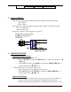
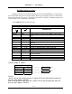
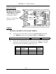
The Relay Option Board
(KKY8924-1) is mounted
to the CPU bd. assy.
on standoffs as shown.
(10) m/f _” standoffs (2per)
(5) panhead screws
WIRING:
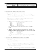
KKY8924-1 BOARD TO CPU BOARD WIRING:
♦ Connect the 20 conductor ribbon cable between J5 EXPANDER on the CPU
assy. (KKR8924-) to J1 on the Analog/Relay/RPM assy. (KKY8924-1).
* Be sure to connect the ribbon cable so that pin 1 of J5 connects to pin 1
of J1.
♦ The two wire red and black cable provides power to the analog assy. The single
in-line plug of this cable plugs into J6 on the CPU assy. (KKR8924 -) and the
black and red wires are terminated at TB2 on the assy.
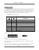
KKY8924-
BOARD
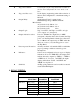
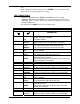
WIRE COLOR CPU
BOARD
+V TB4-4 Red wire J6-1
COM TB4-5 Black wire J6-2
-V TB4-6 White wire J6-4