
User Manual

APPENDIX A - EXAMPLES
A-1
.
EXAMPLE 1(Dual Trip Point )
Require an alarm to be activated when the pressure exceeds 50 PSI and a second alarm to
be activated when the pressure exceeds 75 PSI. The trip points must be able to be entered from
the front panel in the “run” mode. Assume the base mode set for PSI. To eliminate output noise
set the hysteresis for 0.1 PSI when descending.
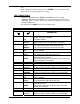
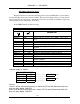
In the TRIP PT menu set the following:
TRIP POINT SELECT MENU
PARAMETER CHOICES
DESCRIPTION
TRIP ON Trip Option enabled
DISPLAY TRIP Display indication for trip point as TRIP x when output
active.
RECALL MODIFY Can view and modify trip point status from front panel.
TRIP 1 ON Trip 1 is enabled.
TYPE 1 TRIP PT Trip Point mode. High trip entry only.
TRIP 1 OVER Sets polarity of trip point 1output to be active over (above)
trip point.
TRIP1.H + 50.00 Trip Point 1 value set for 50 PSI
HYST1.H DESCEND Hysteresis upper trip point 1 applies to descending data.
HYST1.H + 0.10 Hysteresis upper trip point 1 value of 0.01 PSI.
TRIP 2 ON Trip 2 is enabled.
TYPE 2 TRIP PT Trip Point mode. High trip entry only.
TRIP 2 OVER Sets polarity of trip point 2 output to be active over
(above) trip point.
TRIP2.H + 75.00 Trip point 2 value set for 75 PSI
HYST2.H DESCEND Hysteresis upper trip point 2 applies to descending data.
HYST2.H + 0.10 Hysteresis upper trip poiint 2 value set for 0.10 PSI.
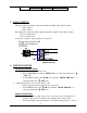
Connect output as follows:
RELAY OPTION BOARD
OUT 1 N.O. TB3-2 ----------------- Alarm 1 --+V
OUT 1 COM TB3-3 ----------------- Ret
OUT 2 N.O. TB3-5 ----------------- Alarm2 --+V
OUT 2 COM TB3-6 ----------------- Ret
Results:
Alarm 1 will be active when pressure is above 50 PSI and will deactivate when the
pressure goes below 49.90 PSI.
Alarm 2 will be active when pressure is above 75 PSI and will deactivate when the
pressure goes below 74.90 PSI.