DLR334 Series TWO RELAYS AND SETPOINTS OPTION OPERATION/INSTALLATION MANUAL PN 74844 .
10/24/01 DLR334 SERIES ADDENDUM 1 TWO RELAYS AND SETPOINTS OPTION OPERATION/INSTALLATION MANUAL TABLE OF CONTENTS SECTION DESCRIPTION PAGE 1 GENERAL INTRODUCTION 1 2 SETPOINTS (TRIP POINTS) DESCRIPTION 1 3 TRIP POINT SPECIFICATIONS 1 4 RELAY WIRING 2 5 LOGIC OUTPUT 2 6 TRIP POINT SETUP 3 7 FRONT PANEL TRIP STATUS INDICATION 4 8 FRONT PANEL TRIP POINT MONITOR AND ENTRY 5 9 SERIAL I/O 6 APPENDIX A EXAMPLES A1 APPENDIX B BOARD INSTALLATION B1 .
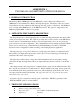
ADDENDUM 1 TWO RELAYS AND SETPOINTS OPTION FOR DLR334 1. GENERAL INTRODUCTION The Analog / Relay / RPM Option board (KKY8924-) can be obtained as a Relay board (KKY8924-1) used with the Two Relays And Setpoint Option. The Option offers two form C relays that are used in conjunction with dual setpoints (trip points) or trip bands. The DLR334 does not support the RPM Option on the KKY8924 board. The option is supported by the DLR334 program KDG-1 version 13 or greater. 2.
♦ ♦ ♦ ♦ ♦ ♦ ♦ ♦ Trip point settability: Set in display (engineering) units with resolution of the base unit configuration. In “run” mode set in base. Trip point Hysteresis: Set in display (engineering) units with resolution of the base unit configuration to a maximum setting of full scale. Output Relay: Arrangement: Form C contact closure.
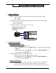
OUT 2 COM OUT 2 COM TB3-6 5. LOGIC OUTPUT: The logic output is available on the 1/0 terminal block TB2 on the CPU assembly. Trip 1: TB2-2 Trip 2: TB2-3 The 1/0 must be selected by jumper plugs P4 and P5 for OUT on the CPU assembly. P4 set for OUT at S4 P5 set for OUT at S5 A trip “ON” condition “relay energized” is a logic “0” Jumper plugs shown on S4 and S5 are configured as OUTPUTS. S5 I/O 2 OUT IN I/O 1 S4 RETURN TB2 (digital common) 6. TRIP POINT SETUP SELECTING TRIP PT SETUP: 1.
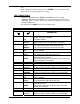
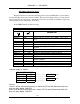
• keys. After entering the desired value press the “ENTER” key to accept this value. Step to the next set up using the down ⇓ key. TRIP PT MENU TABLE • The Lower Trip Band value (TRIP1.L and TRIP2.L) and associated parameters (HYST1.L and HYST2.L) do not appear in the menu when the “TRIP PT” Type is selected. The Lower value is automatically set for minus full range in this mode • The parameters in BOLD letters are the default values.
HYST2.H HYST2.L HYST2.L ±XXXXX0 DESCEND ASCEND ±XXXXX0 Hysteresis upper trip point 2 value. Hysteresis lower trip point 2 applies to descending data. Hysteresis lower trip point 2 applies to ascending data. Hysteresis lower trip point 2 value. 7. FRONT PANEL TRIP STATUS INDICATION: Display select: The Trip Status can be monitored in the run mode by using the “DISPLAY” key to step to the trip status display. The units will only be displayed momentarily when changed by the unit selection key.
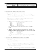
"DISPLAY" parameter to "MODIFY" in the "TRIP PT” Menu". TRIP POINT VALUE RECALL: Recall the Trip Point values by pressing the "DISPLAY" key in the run mode until the trip point prompts (triPl.H, tripl L, triP2.H or triP2.L) are indicated. The Trip Point values are expressed in the current selected pressure display units. Trip Point values are entered in Base Mode Units. DISPLAY RECALLED TRIP VALUES Display Prompt TriP1.H TriP1.L TriP2.H TriP2.
. SERIAL I/O All Trip point menu parameters can be recalled or entered via the Serial Full Duplex when in the setup mode. For full details of the trip point serial I/O refer to the DLR334 Duplex Serial Protocol document. 7 .
APPENDIX A - EXAMPLES EXAMPLE 1(Dual Trip Point ) Require an alarm to be activated when the pressure exceeds 50 PSI and a second alarm to be activated when the pressure exceeds 75 PSI. The trip points must be able to be entered from the front panel in the “run” mode. Assume the base mode set for PSI. To eliminate output noise set the hysteresis for 0.1 PSI when descending.
APPENDIX A - EXAMPLES EXAMPLE 2 (Trip Band ) Require an alarm to be activated when the pressure falls out of an acceptance band of 25 PSI to 50 PSI. The trip points must be able to be entered from the front panel in the “run” mode. Assume the base mode set for PSI. To eliminate output noise set the hysteresis for 0.1 PSI . Require a front panel status display to indicate when the pressure is acceptable or high or low. For failsafe it is required that the alarm will sound if the indicator losses power.
APPENDIX A - EXAMPLES When the pressure is under 25 PSI, the display will prompt with “LOW” and the output alarm will be active. The alarm will be inactive when the pressure rises over 25.1 PSI. A-3 .
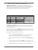
APPENDIX B - INSTALLATION INSTALLATION The Relay Option Board (KKY8924-1) is mounted to the CPU bd. assy. on standoffs as shown. (10) m/f _” standoffs (2per) (5) panhead screws WIRING: KKY8924-1 BOARD TO CPU BOARD WIRING: ♦ Connect the 20 conductor ribbon cable between J5 EXPANDER on the CPU assy. (KKR8924-) to J1 on the Analog/Relay/RPM assy. (KKY8924-1). * Be sure to connect the ribbon cable so that pin 1 of J5 connects to pin 1 of J1.