Conceptronic CADSLR4+ Annex A/B Version 4.
Table of Contents Specification ................................................................Error! Bookmark not defined. Package Contents ...................................................................................................... 5 Hardware Connecting................................................................................................. 6 LED Indicators ............................................................................................................ 7 General Setting.....
Egress ...........................................................Error! Bookmark not defined. Shaper........................................................................................................ 38 Web Access Control ................................................................................... 39 Web Access Control ................................................................................... 39 SSH Access Control ........................................................................
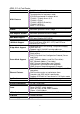
ADSL 2/2+ 4 Port Router Line Connection ADSL Features Full-rate adaptive modem G.lite adaptive modem WAN Mode Support LAN Mode Support Bridge Mode Support Router Mode Support Ethernet Features Certification OS System Requirement Power LED Indication PCB SIZE Software Upgrade RJ-11(2 wires), RJ-45 (4 port) DMT modulation and demodulation Tone detection for low power mode ATM SAR performed in software driver ITU 992.1 (G.dmt) Annex A, B, ITU 992.2 (G.lite) ITU 992.3 ADSL2 (G.dmt.bis) ITU 992.
Application Diagram ADSL Internet 4
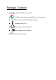
Package Contents Conceptronic CADSLR4+ Annex A/B CD-ROM containing Manual and USB Driver for one port router Ethernet Cable (CAT5 UTP Straight-Through) Telephone Cable (RJ11) USB Cable only for one port router Power Adapter (12VAC 800mA) Quick Installation Guide 5
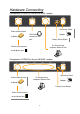
Hardware Connecting Conceptronic CADSLR4+ Annex A/B ADSL modem Connect to Power Phone cable connect USB Cable to Splitter Adapter connect to USB port Factory Reset Button RJ-45 connect to computer Ethernet Port Phone Cable connect to wall phone jack Conceptronic CADSLR4+ Annex A/B ADSL modem Connect to Power Phone cable connect RJ-45 connect to computer Ethernet Port Adapter to Splitter Factory Reset Button Phone Cable connect to wall phone jack 6
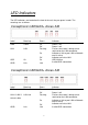
LED Indicators The LED Indicators are located on the front of the unit, they are green in color. The meanings are as follows: Conceptronic CADSLR4+ Annex A/B Label Meaning Status Indicates PWR Power LAN LAN On Off Flashing Off Power is on Power is off Flashes when data is being sent or received on the LAN connection. Indicates a link to your LAN or Network card is active. Indicates no link to LAN On Link USB initialize A valid ADSL connection.
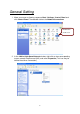
General Setting 1. Move your cursor as flowing sequence Start \ Settings \ Control Panel and click Control Panel. Then double-click on the Network Connections Double Click on this icon 2. In the LAN or High-Speed Internet window, right-click on icon corresponding to your network interface card (NIC) and select Properties.(This icon may be labeled Local Area Connection).
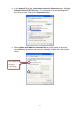
3. In the General Tab of the Local Area Connection Properties menu. Highlight Internet Protocol (TCP/IP) under “This connection uses the following items.” by click on it once. Click on the Properties button. 4. Select Obtain an IP Address automatically: by clicking once in the circle. Click OK button to confirm and save your changes, and the close the Control Panel.
5. Release IP & Renew IP, then Check Default Gateway: 192.168.1.1. 6. Launch your PC web browser and enter the URL: http://192.168.1.1 7. In the User name/Password prompt, please type in Admin/Admin as default.
8. After Login procedure the Quick Start page will appear. - 1 2 3 4 XSelect country from the drop-down list. YSelect ISP from the drop-down list. ZSelect Encapsulation from the drop-down list. [The VPI and VCI value will automatically set up ok. Then click Next. rIf you can’t find your ISP setting, please click Config.
Advanced Setup Setup The Setup section allows you to create new connections, edit existing connections, and configure other basic settings. LAN Setup LAN Configuration The following is displayed LAN Setup. IP Address: Private IP address for connecting to a local private network (Default: 192.168.1.1). Netmask: Netmask for the local private network (Default: 255.255.255.0). Default Gateway: This field is optional. Enter in the IP address of the router on your network. Host Name: Required by some ISPs.
Start IP: Sets the start IP address of the IP address pool. End IP: Sets the end IP address of the IP address pool. Lease time: The lease time is the amount of time of a network user will be allowed to connect with DHCP server. If all fields are 0, the allocated IP address will be effective forever. Click Apply to complete the setup. Click Save All to save the changes.
Ethernet Switch This Ethernet Switch Configuration page allows you to set value for data transfer; Physical Port: There are five kinds of mode for data transfer (Auto)(10/Half Duplex)(10/Full Duplex)(100/Half Duplex)(100/Full Duplex). Click Apply to complete the setup. Click Save All to save the changes.
WAN Setup New Connection When working with wide area connections, the first thing you must do is to have the handle of the connection. Once you have the handle for a Connection you must define the PVC and protocol settings for it. Name: Enter the name of your ISP. This information is for identification purposes only. Type: There six kinds of method (PPPoE/ PPPoA/ Static/ DHCP/ Bridge/ CLIP). Encapsulation: Select you encapsulation type. (Supplied by your ISP).
• Idle Timeout • Host Trigger • Valid Rx Default Gateway: If checked, this WAN connection acts as the default gateway to the Internet. Enforce MTU: This feature is enabled by default. It forces all TCP traffic to conform with PPP MTU by changing TCP maximum segment size to PPP MTU. If it is disabled, you may have issues accessing some Internet sites. Debug: Enables PPPoE connection debugging facilities.
auto-sensing PVC feature relies on end-to-end OAM pings to defined PVCs. There are two groups of PVCs: customer default PVCs which are defined by the OEM/ISP and the backup PVCs. The customer default must have 0/35 as the first default PVC. The backup list of PVCs must be of the following VPI/VCI: 0/35, 8/35, 0/43, 0/51, 0/59, 8/43, 8/51, and 8/59. The list of PVCs are defined in XML and is configurable.
PPPoE Settings 1. 2. 3. At the Setup main page, click New Connection. At the Type field select PPPoE. In the Name field, enter a unique name for the PPPoE connection. The name must not have spaces and cannot begin with numbers. 4. The Network Address Translation (NAT) and the Firewall options are enabled by default. Leave these in the default mode. 5. 6. 7. 8. 9. Note—NAT enables the IP address on the LAN side to be translated to IP address on the WAN side.
• VLAN: The VLAN ID and Priority Bits fields are activated when VLAN is selected, which enable you to create VLAN. VLAN ID VLAN Identification. Multiple connections over the same PVC are Supported, which requires the WAN network to have VLAN support and for the DSLAMS and Routers on the ISP to handle VLAN Tags. Extended support is also available, which allows multiple connections to be placed over the single PVC without VLAN support (VLAN Tag of 0 is this special case).
PPPoA Settings 1. 2. 3. At the Setup main page, click New Connection. At the Type field select PPPoA. Enter a unique name for the PPPoA connection in the Name field. The name must not have spaces and cannot begin with numbers. 4. The Network Address Translation (NAT) and the Firewall options are enabled by default. Leave these in the default mode. If you want to enable VLAN, use the reference to configure the following fields: 5. 6. 7. 8. 9.
• VLAN: The VLAN ID and Priority Bits fields are activated when VLAN is selected, which enable you to create VLAN. VLAN ID VLAN Identification. Multiple connections over the same PVC are Supported, which requires the WAN network to have VLAN support and for the DSLAMS and Routers on the ISP to handle VLAN Tags. Extended support is also available, which allows multiple connections to be placed over the single PVC without VLAN support (VLAN Tag of 0 is this special case).
Static Settings 1. 2. 3. At the Setup main page, click New Connection. At the Type field select Static. In the Name field, enter a unique name for the Static connection. The name must not have spaces and cannot begin with numbers. 4. The Network Address Translation (NAT) and the Firewall options are enabled by default. Leave these in the default mode. 5. In the Static Settings section, select the Encapsulation Type (LLC or VC). Note— If you are not sure, just use the default mode.
DHCP Settings 1. 2. 3. At the Setup main page, click New Connection. At the Type field select DHCP. Enter a unique name for the DHCP connection in the Name field. The name must not have spaces and cannot begin with numbers. 4. The Network Address Translation (NAT) and the Firewall options are enabled by default. Leave these in the default mode. If your DSL line is connected and your DSL/IPS provider is supporting DHCP, you 5.
Bridge Settings 1. 2. 3. At the Setup main page, click New Connection. At the Type field select Bridge. Enter a unique name for the Bridged connection in the Name field. The name must not have spaces and cannot begin with numbers. 4. In the Bridge Settings section, select the Encapsulation Type (LLC or VC). Note— If you are not sure, just use the default mode. In the PVC Settings section, enter values for the VPI and VCI. Note—Your DSL service provider or your ISP supplies these values.
CLIP Settings 1. 2. 3. At the Setup main page, click New Connection. At the Type field select CLIP. Enter a unique name for the static connection in the Name field. The name must not have spaces and cannot begin with numbers. 4. The Network Address Translation (NAT) and the Firewall options are enabled by default. Leave these in the default mode. 5. Based upon the information your DSL/ISP provided, enter your assigned IP Address, Mask, ARP Server, and Default Gateway.
Modem This page allows you Select ADSL Transmission Type. ADSL_ANSI_T.1413: Full-Rate (ANSI T1.413 Issue 2) with line rate support of up to 8 Mbps downstream and 832 Kbps upstream. ADSL_G.dmt: Full-Rate (G.dmt, G992.1) with line rate support of up to 8 Mbps downstream and 832 Kbps upstream. ADSL_G.lite: G.lite (G.992.2) with line rate support of up to 1.5 Mbps downstream and 512 Kbps upstream. MULTI_MODE: Support Multi-Mode standard (ANSI T1.413 Issue 2; G.dmt(G.992.1); G.lite(G.992.2)).
ADVANCED UPnP Universal plug and play (UPnP), NAT, and firewall traversal allow traffic to pass through the RG for applications using the UPnP protocol. This feature requires one active WAN connection. In addition, the PC should support this feature. In the presence of multiple WAN connections, select a connection on which the incoming traffic is present, for example, the default WAN connection. 1. Check Enable UPnP. This enables the WAN Connection and LAN Connection fields. 2.
SNTP The Router keeps time by connecting to a Simple Network Time Protocol (SNTP) server. This allows the Router to synchronize the system clock to the global Internet. The synchronized clock in the Router is used to record the security log and control client filtering. Primary SNTP Server: Enter the SNTP Server address. Default is 0.0.0.0. Secondary SNTP Server: Enter the SNTP Server address. Default is 0.0.0.0. Tertiary SNTP Server: Enter the SNTP Server address. Default is 0.0.0.0.
Port Forwarding The port forwarding feature allows you to direct incoming traffic to specific LAN hosts based on a protocol port number and protocol. Using the Port Forwarding page, you can provide local services (for example, web hosting) for people on the Internet or play Internet games. Port forwarding is configurable per LAN group. A database of predefined port forwarding rules allows you to apply one or more rules to one or more members of a defined LAN group.
DMZ This DMZ Settings page allows you Enable or Disable this function. This function is disabled by default. By enabling DMZ, you add an extra layer of security protection for hosts behind the firewall. Enable DMZ Function. Enable DMZ: Enables/disables the Demilitarized Zone feature. This field is unchecked (disabled) by default. Select your WAN Connection: Select the WAN connection on which the DMZ feature is applied. Select LAN Group: Select the LAN Group on which the DMZ feature is applied.
Custom Port Forwarding The Custom Port Forwarding page allows you to create up to 15 custom port forwarding entries to support specific services or applications, such as concurrent NAT/NAPT operation. Connection: Select the WAN connection on which the Custom Port Forwarding rule is to be applied. Enable: The Enable button is checked by default, meaning this rule is automatically applied when you click the Apply button. Application: Name of the application for which your ports will be opened.
IP Filter The IP filtering feature allows you to block specific applications/services based on the IP address of a LAN device. You can use the IP Filters page to block specific traffic (for example, block web access) or any traffic from a host on your local network. A database of predefined IP filters allows you to apply one or more filtering rules to one or more members of a defined LAN group. You can view the rules associated with a predefined filter and add the available rules for a given category.
• Protocol • TCP • UDP • TCP and UDP • ICMP • Any Filter Name: Name of the IP filter rule you are creating. Enable: The Enable button is checked by default, meaning this rule is automatically applied when you click Apply. Source IP: The LAN-side source IP address assigned to outgoing traffic on which filtering is applied. Source Netmask: Netmask of the source IP on your LAN side. Destination IP: You can define the destination IP address to which your source IP will be banned access. Enter 0.0.0.0 for all.
LAN Clients The LAN clients feature allows you to see all the hosts on the LAN segment. Each host is qualified to be either dynamic (host obtained a lease from this RG) or static (host has a manually-configured IP address). Select LAN Connection: Select the LAN connection to which the client is to be added. Enter IP Address: Assign the dynamic IP address to the host here. This is a mandatory field. Hostname: Hostname of the client. This is an optional field. MAC Address: MAC address of the host.
Dynamic DNS Client The Dynamic DNS Client page allows you to enable/disable the Dynamic DNS feature. Connection: This field defaults to your RG’s WAN connection over which your RG will be accessed. DDNS Server: This is where you select the server from different DDNS service providers. A charge may occur depends on the service you select. DDNS Client: Enables/disables the DDNS client feature for the WAN connection. This field is disabled by default.
IGMP Proxy The IGMP Proxy page allows you to enable multicast on available WAN and LAN connections. You can configure the WAN or LAN interface as one of the following: Upstream: The interface that IGMP requests from hosts is sent to the multicast router. Downstream: The interface data from the multicast router are sent to hosts in the multicast group database. Ignore: No IGMP request nor data multicast are forwarded. Click Apply to complete the setup. Click Save All to save the changes.
Static Routing The Static Routing page enables you to define routes for specific subnets on the WAN/LAN side. The RG allows you to manually program the RG's routing table. Up to 16 static routes can be added. Choose a Connection: Select the LAN group or WAN connection to which a static routing subnet is to be applied. New Destination IP: The network IP address of the subnet. (You can also enter the IP address of each individual station in the subnet). Mask: The network mask of the destination subnet.
Shaper The Shaper Configuration page is accessed by selecting Shaper on the Advance main page. Interface: The selections are WAN/LAN interfaces except WLAN, which does not support Shaper feature. This field needs to be selected before shaper configuration. Max Rate: This field is applicable for the HTB Queue Discipline and Low Latency Queue Discipline; both are rate-based shaping algorithms. HTB Queue Discipline: The hierarchical token bucket queue discipline is a rate-based shaping algorithm.
Web Access Control The Web Access Control page allows you to access the RG remotely via the web from the WAN side. Enable: Enables/disables the remote web access feature. Choose a Connection: Select the WAN connect over which the remote web access feature is enabled. Remote Host IP: Enter the IP address of the remote host. Remote Netmask: Enter the netmask of the remote host. Redirect Port: You can enter a port number in this field that is different from the well-known IP port number 80.
SSH Access Control The SSH Access Control page allows you to access the RG remotely via SSH from the WAN side. Enable: Enables/disables the remote web access feature. Choose a Connection: Select the WAN connect over which the remote web access feature is enabled. Remote Host IP: Enter the IP address of the remote host. Remote Netmask: Enter the netmask of the remote host. Click Apply to complete the setup. Click Save All to save the changes.
TOOLS The Tools section allows you to save the configuration, restart the gateway, update the gateway firmware, setup user and remote log information and run Ping and Modem tests. System Commands System Commands allow you to carry out basic system actions, Press the button to execute a command.
Remote Log-Router The Router Table page displays routing table and allows the user to manually enter the routing entry. The routing table will display the routing status of Destination, Netmask, Gateway and Interface. The interface br0 means the USB interface; Io0 means the loopback interface and ppp1 means the PPP interface. The Gateway is the learned Gateway. Click Apply to complete the setup. Click Save All to save the changes.
User Management User Management is used to change your User Name or Password. User Name: Default is ‘Admin’. You can enter your new user name here. Password: Default is ‘Admin’. You can enter your new password here. Confirmed Password: Enter your new password here again to confirmed. Idle Timeout: The default is 30minutes. You will need to log back onto the RG after your session has been inactive for 30 minutes. You can change the timeout here. Click Apply to complete the setup.
Firmware Upload To update your gateway firmware, choose an update image (Kernel/ File system) or configuration file In Select a File, and then click the Update Gateway button. Additionally, you may download your configuration file from the system by clicking Get Configuration. Ping Test Packet INternet Groper is protocol that sends out ICMP echo requests to test whether or not a remote host is reachable.
Modem Test The Modem Test page is used to check the connectivity to the WAN. This test may take a few seconds to complete. Before running this test, make sure you have at least one WAN connection configured and have a valid DSL link. If the DSL link is not connected, the test will fail. Also make sure the DSLAM supports this feature. Not all DSLAMs have F4 and F5 support. F4/F5 cells are used for operation, administration, and maintenance (OAM) on ATM level.
STATUS The Status section allows you to view the Status/Statistics of different connections and interfaces. Network Statistics The Ethernet Network Statistics page shows the statistics for the Ethernet connection. The DSL Network Statistics page shows the statistics for the DSL connection. The Wireless Network Statistics page shows the statistics for the Wireless connection.
Connection Status The Connection Status page shows the status of PPP for each PPP interface. DHCP Clients The DHCP Clients page shows the MAC Address, IP Address, Host Name and Lease Time.
Modem Status The Modem Status page shows the modem status and DSL statistics. Product Information The Product Information page shows the product information and software versions.
System Log The System Log page shows the events triggered by the system.
HELP This section takes you to different Help Sections for Firewall, Bridge Filters, LAN Clients and PPP Connection. Firewall Help Help for Port Forwarding, Access Control, and Advanced Security. Bridge Filter Help Help section for Bridge Filters.
51
LAN Clients Help Help section for LAN Clients. LAN Configuration Help Help section for LAN Configuration.
PPP Connection Help Help for establishing a PPP Connection. UPnP Help Help pages for UPnP.
RIP Help Help section for RIP (Routing Information Protocol).
Troubleshooting This chapter gives information about troubleshooting your ADSL Router. After each problem description, instructions are provided to help you diagnose and solve the problem. For the common problems listed, go to the section indicated. Is the router on? Have I connected the router correctly? Go to Basic Functioning. I can't access the router's configuration with my browser. Go to Troubleshooting the Web Configuration Interface.
If all LEDs are still on one minute after power up: Cycle the power to see if the router recovers. Clear the router's configuration to factory defaults. This will set the router's IP address to 192.168.1.1. If the error persists, you might have a hardware problem and should contact technical support.
Using the Reset button. Make sure your browser has Java, JavaScript, or ActiveX enabled. If you are using Internet Explorer, click Refresh to be sure the Java applet is loaded. Try quitting the browser and launching it again. Make sure you are using the correct login information. The factory default login name is Admin and the password is Admin. Make sure that CAPS LOCK is off when entering this information.
If the telephone company has tested the ADSL signal at your Network Interface Device (NID), then you may have poor quality wiring in your house. If disconnecting telephones does not result in a green WAN LED the problem may be one of the following: Check that the telephone company has made the connection to your line and tested it. Verify that you are connected to the correct telephone line. If you have more than one phone line, be sure that you are connected to the line with the ADSL service.
Assign the computer Host Name of your ISP account to the router in the browser-based Setup Wizard. Your ISP only allows one Ethernet MAC address to connect to Internet, and may check for your computer's MAC address. In this case: Inform your ISP that you have bought a new network device, and ask them to use the router's MAC address. Or configure your router to spoof your computer's MAC address. This can be done in the Basic Settings menu.
and verify the router address. Troubleshooting a TCP/IP Network Using the Ping Utility Most TCP/IP terminal devices and routers contain a ping utility that sends an echo request packet to the designated device. The device then responds with an echo reply. Troubleshooting a TCP/IP network is made very easy by using the ping utility in your computer. Testing the LAN Path to Your Router You can ping the router from your computer to verify that the LAN path to your router is set up correctly.
From the Windows run menu, type: ping -n 10 where is the IP address of a remote device such as your ISP's DNS server. If the path is functioning correctly, replies as in the previous section are displayed. If you do not receive replies: — Check that your PC has the IP address of your router listed as the default router. If the IP configuration of your PC is assigned by DHCP, this information will not be visible in your PC's Network Control Panel.
Appendix Country Australia ISP All Internet providers PVC VPI:8 VCI:35 VPI:0 Belgium VCI:33 Canada VPI:0 Telus VCI:35 Cybercity VPI:8 VCI:35 Danmark Tiscali VPI:8 VCI:35 1 & 1 Internet DSL VPI:1 VCI:32 AOL DSL VPI:1 VCI:32 Arcor DSL VPI:8 VCI:35 Freenet DSL VPI:1 VCI:32 Fireline networks VPI:1 VCI:32 Deutschland GMX Internet VPI:1 VCI:32 Hansenet VPI:8 VCI:35 Netcologne VPI:8 VCI:35 Schlund VPI:1 VCI:35 Snafu ADSL VPI:1 VCI:32 Tiscali VPI:1 VCI:32 T-online VPI:1 VCI:32 And
Country ISP Wannadoo France Tiscali ISRAEL KPN PPPoE LLC Telecom Italia Italian Rest oil presente KPN PPPoA VC-MuX Netherlands BBeyond Bridge LLC BBeyond PPPoA VC-MuX New Zealand New Zealand Telecom Portugal Todos os apresentador Albura Spanish Colt Teeccom Earth Eresmas Jazztel Ola Internet Retevision Terra Spanish Tiscali Telefornica Telepac Uni2 Ya.
Country ISP Island ssimi Suomi Landssimi Vortex Switserland Alle anbieter Sverige Skanova Hinet Taiwan Seednet Etisalat Classical IP Single User United Arab Emirates United Kingdom Etisalat Classical IP for Business British Telecom 64 PVC VPI:0 VCI:35 VPI:8 VCI:48 VPI:8 VCI:48 VPI:1 VCI:32 VPI:8 VCI:35 VPI:0 VCI:33 VPI:0 VCI:33 VPI:8 VCI:35 VPI:8 VCI:35 VPI:0 VCI:38