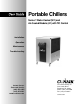
Portable Chillers Series 1 Water-Cooled (W1) and Air-Cooled Models (A1) with TIC Control Installation Operation Maintenance Troubleshooting Instant Access Parts and Service (800) 458-1960 (814) 437-6861 www.conairnet.com The Conair Group, Inc.
Please record your equipment’s model and serial number(s) and the date you received it in the spaces provided. It’s a good idea to record the model and serial number(s) of your equipment and the date you received it in the User Guide. Our service department uses this information, along with the manual number, to provide help for the specific equipment you installed. Please keep this User Guide and all manuals, engineering prints and parts lists together for documentation of your equipment.
INTRODUCTION . . . . . . . . . . . . . . . . . . .1-1 Purpose of the User Guide . . . . . . . . . . . . . . . . . . . . . . . . .1-2 How the Guide is Organized . . . . . . . . . . . . . . . . . . . . . . .1-2 Your Responsibilities as a User . . . . . . . . . . . . . . . . . . . . .1-2 ATTENTION: Read this so no one gets hurt . . . . . . . . . . .1-3 TABLE OF CONTENTS DESCRIPTION . . . . . . . . . . . . . . . . . . . .2-1 What is the Portable Chiller? . . . . . . . . . . . . . . . . . . . . . . .
TABLE OF CONTENTS MAINTENANCE . . . . . . . . . . . . . . . . . . . .5-1 Maintenance Features . . . . . . . . . . . . . . . . . . . . . . . . . . . .5-2 Warnings and Cautions . . . . . . . . . . . . . . . . . . . . . . . . . . .5-3 Preventative Maintenance Schedule . . . . . . . . . . . . . . . . . .5-4 Checking the Refrigerant Charge . . . . . . . . . . . . . . . . . . . .5-6 Cleaning the Evaporator or Water-cooled Condenser . . . . .5-7 Cleaning the Air-cooled Condenser . . . . . . . . . . . . . . . . .
INTRODUCTION ● Purpose of the User Guide . . . .1-2 ● How the guide is organized . . . .1-2 ● Your responsibilities as a user .1-2 ● ATTENTION: Read this so no one gets hurt . . . . . . . . . . .
PURPOSE OF THE USER GUIDE This User Guide describes Conair’s Series 1 Water-cooled and Air-cooled Portable Chillers and explains step-by-step how to install, operate, maintain and repair this equipment. HOW THE GUIDE IS ORGANIZED Symbols have been used to help organize the User Guide and call your attention to important information regarding safe installation and operation.
We design equipment with the user’s safety in mind. You can avoid the potential hazards identified on this machine by following the procedures outlined below and elsewhere in the User Guide. ATTENTION: READ THIS SO NO ONE GETS HURT WARNING: Improper installation, operation, or servicing may result in equipment damage or personal injury.
DESCRIPTION ● What is the Portable Chiller? . . .2-2 ● Typical Applications . . . . . . . . . .2-3 ● Limitations . . . . . . . . . . . . . . . . .2-3 ● How it Works: Water-cooled Portable Chiller . . . . . . . . . . . .2-4 ● How it Works: Air-cooled Portable Chiller . . . . . . . . . . . .2-6 ● Portable Chiller Features . . . . . .2-8 ● Specifications . . . . . . . . . . . . .2-10 ● Pump Curves . . . . . . . . . . . . . .
WHAT IS THE PORTABLE CHILLER? The Conair Series 1 Portable Chillers provide self-contained sources of chilled water and are available in either water- or air-cooled models, ranging in sizes from 3.5 Hp to 40 Hp (approximate capacities of 3.5 tons of refrigeration to 40 tons of refrigeration). Pump selections are available to match most process flow and pressure requirements. The normal temperature range of discharge chilled water is 20 °F to 70 °F.
The Conair A1 and W1 Portable Chillers can be used anywhere a reliable source of process cooling water - with stable temperature control - is required. TYPICAL APPLICATIONS These portable chillers are available for cooling injection molding, blow molding, thermoforming, extrusion, air compressors, metal plating, anodizing, degreasing, heatset/web offset printing presses, and dryer after-coolers. Roll the air-cooled condenser models next to the heat source connect it and plug it in.
Process circulation HOW IT WORKS: WATER-COOLED PORTABLE CHILLER 1 Hot fluid from the process enters the chiller through the From Process valve into the pump reservoir. 2 is chilled in the 3 Fluid evaporator and exits through the to Process valve and tube, returning to the process. 2-4 DESCRIPTION Pump draws water from pump reservoir and moves it through the strainer and flow switch to the evaporator.
Refrigerant circulation 4 The liquid refrigerant leaves the accumulator, passing through the thermal expansion valve, where it expands and cools. HOW IT WORKS: WATER-COOLED CONT’D high pressure vapor travels from 3 The the compressor through the coiled condenser (where it is condensed into a liquid) and is stored in the accumulator. refrigerant 2 Vaporized travels from evaporator to the compressor, where the low pressure vapor is compressed into a high pressure vapor.
Process circulation HOW IT WORKS: AIR-COOLED PORTABLE CHILLER 1 Hot fluid from the process enters the chiller through the From Process valve into the pump reservoir. is chilled in the 3 Fluid evaporator and exits through the To Process valve and tube, returning to the process. 2-6 DESCRIPTION Pump draws fluid from pump reservoir and moves it through the strainer and flow switch to the evaporator.
Refrigerant circulation 4 The liquid refrigerant leaves the accumulator, passing through the thermal expansion valve, where it expands and cools. HOW IT WORKS: AIR-COOLED PORTABLE CHILLER 3 The high pressure vapor travels from the compressor through the condenser (where fans cool vapor into a liquid) and liquid is stored in the accumulator. refrigerant 2 Vaporized travels from evaporator to the compressor, where the low pressure vapor is compressed into a high pressure vapor.
PORTABLE CHILLER FEATURES Water-cooled Models Condenser Relief valve acts as a safety device for refrigerant pressure. compresses the refrigerant from a high pressure vapor into a high pressure liquid. Compressor compresses the refrigerant from a low pressure vapor into a high pressure vapor. Hot Gas Bypass valve balances the load on the chiller to meet the needs of the process. Liquid line solenoid valve pumps down refrigerant to the receiver. Receiver stores the liquid refrigerant.
Air-cooled Models Condenser compresses the refrigerant from a high pressure vapor into a high pressure liquid. PORTABLE CHILLER FEATURES Fans circulate air across the condenser to cool refrigerant Compressor compresses the refrigerant from a low pressure vapor into a high pressure vapor. Hot Gas Bypass valve balances the load on the chiller to meet the needs of the process. Temperature transmitter electrical box Receiver stores the liquid refrigerant.
Water-cooled Models SPECIFICATIONS side front back F A 10.5 {267} D E 5.
Air-cooled Models SPECIFICATIONS front back side A 10.5 {267} 5.
PUMP CURVES Pressure (psi) 60 HZ PUMP PERFORMANCE CURVES Flow Rate (gpm) Pressure (psi) 50 HZ PUMP PERFORMANCE CURVES Flow Rate (gpm) 2-12 DESCRIPTION Series 1 Portable Chillers, TIC Control UGH016/0500
INSTALLATION ● Unpacking the Boxes . . . . . . . . . .3-2 ● Warnings and Cautions . . . . . . . . .3-3 ● Preparing for Installation . . . . . . .3-4 ● Making Process Plumbing Connections . . . . . . . . . . . . . . . .3-5 ● Filling the Chiller . . . . . . . . . . . . . .3-6 ● Checking Refrigerant Charge . . . .3-8 ● Connecting the Main Power Source . . . . . . . . . . . . . . .3-9 ● Checking Electrical Connections . . . . . . . . . . . . . . .3-10 ● Initially Starting the Chiller . . . . .
UNPACKING THE BOXES The portable chiller comes fully assembled in a single crate. CAUTION: Lifting hazard The Series 1 Portable Chillers are designed to easily roll on casters. If, for some reason you need to lift the chiller, take all precautions to avoid personal injury or damage to the chiller. Lift the chiller using a forklift or hoist with straps that have peen positioned at the chillers’ center of gravity. Do not try to lift the unit manually. 1 Carefully uncrate the chiller and its components.
WARNING: Improper installation, operation, or servicing may result in equipment damage or personal injury. This equipment should only be installed, adjusted, and serviced by qualified technical personnel who are familiar with the construction, operation, and potential hazards of this type of machine. WARNINGS CAUTIONS AND All wiring, disconnects and fuses should be installed by qualified electrical technicians in accordance with electrical codes in your region. Always maintain a safe ground.
PREPARING FOR INSTALLATION Plan the location for the chiller and prepare the area properly. Position the Chiller as close to the process machine as possible. Place the chiller in position near the process machine so that fluid lines can be connected from the process machine to the chiller and back. Chiller Process machine Alternate locations Make sure the area where the chiller is installed has: ● A grounded power source. Check the chiller’s serial tag for the correct amps, voltage, phase, and cycle.
Warm fluid from your process enters the chiller at the From Process valve and chilled fluid returns to the process equipment through the To Process valve. 1 Remove the shipping plastic pipe plug from the female connections on the back of the portable chiller. 2 Make sure the male pipe threads are clean MAKING PROCESS PLUMBING CONNECTIONS and new. 3 4 Wrap threads with Mylar or Teflon tape. Connect the From Process valve and tubing on the back of the chiller to the From Process tubing.
The Chiller is shipped without coolant. The chiller is filled manually during installation. Use water as the coolant down to 40 °F (4 °C). Below 40 °F and down to 20 °F (-7 °C), use an ethylene glycol or propylene glycol solution. FILLING THE CHILLER To fill with water: 1 2 3 Attach water hose to Fill/Drain valve. Close the To Process and From Process valves. Open the Fill/Drain valve and fill chiller to the fill mark on the Water Level sight glass.
FILLING THE CHILLER Glycol, % by Volume CONT’D Temperature of Process Fluid °F 2 3 Close the To Process and From Process valves. Open the Fill/Drain valve and fill chiller to the fill mark on the Water Level gauge. If the chiller is overfilled, the excess fluid spills out the vent tube. DO NOT OVERFILL. 4 5 Close the Fill/Drain valve. Check the coolant level. Once the chiller is turned on, the coolant level may drop as the coolant begins to circulate, filling the connected plumbing.
CHECKING REFRIGERANT CHARGE All chillers are fully charged with refrigerant at the factory. Your chiller’s model nameplate identifies the type and amount of total refrigerant charge required. Check refrigerant charge while the chiller is running. Check the refrigerant charge through the sight glass. Open the side door of the Chiller. Use a flashlight, if necessary, and check the liquid-line sight glass: ● Under normal load conditions, the refrigerant should be clear.
WARNING: Improper installation, operation, or servicing may result in equipment damage or personal injury. This equipment should only be installed, adjusted, and serviced by qualified technical personnel who are familiar with the construction, operation, and potential hazards of this equipment CONNECTING THE MAIN POWER SOURCE All wiring, disconnects and fuses should be installed by qualified electrical technicians in accordance with electrical codes in your region. Always maintain a safe ground.
CHECKING ELECTRICAL CONNECTIONS WARNING: Electrical hazard Before performing any work on this item, disconnect and lock out electrical power sources to prevent injury from unexpected energization or startup. 1 2 Open electrical enclosure. Connect the power cable to the main line connection. 3 Check the short-to-ground with an ohm meter. Connect the ohm meter to each of the three terminal screws and to the grounding lug. Test all three for resistance. The minimum resistance to ground should be 1megohm.
1 Turn on main power source. The control boots up and the screen displays the temperature of the fluid going to the process. WARNING: Initial startup INITIALLY STARTING THE CHILLER Do not press any buttons after initially applying power to the Chiller. Let the Chiller set, undisturbed, for a minimum of 8 hours before starting the Chiller. This is necessary to allow the crankcase heater to warm properly, and to prevent the refrigerant from pooling in the compressor.
STOPPING THE CHILLER To stop the chiller, press the Stop Chiller button on the control panel. NOTE: When you press the Stop Chiller button, the pump and compressor both stop. If you want to restart immediately by pressing the Start Chiller button, the pump will turn on but the compressor will not turn on for three minutes. The Process Pump light on the control panel will light immediately. After three minutes the compressor turns on and the Compressor light on the control panel lights.
OPERATION ● TIC Control Features . . . . . . . . .4-2 ● Before Starting . . . . . . . . . . . . . .4-3 ● Starting/Stopping the Chiller . . .4-4 ● Changing Settings . . . . . . . . . . .4-5 ● Changing the Setpoint Temperature . . . . . . . . . . . . . .4-6 ● Changing Temperature Scale . .4-7 ● Changing Auto Tune Mode . . . .4-7 ● Setting the To Process Low Limit . . . . . . . . . . . . . . . . .
TIC CONTROL FEATURES The TIC control lets you view the status of the chiller and change settings. Display System lights 4-digit LED screen shows To Process temperature, new settings and run modes. Indicator light shows hot gas unloading.
Before you start daily operation of the chiller, you need to perform scheduled preventative maintenance. Necessary maintenance is describe in the Maintenance section of this Users Guide. BEFORE STARTING WARNING: Electrical hazard Be sure that power to the chiller is OFF when doing any maintenance on the chiller. Follow all safety rules when performing any maintenance on this equipment.
STARTING/ STOPPING THE CHILLER Plug in the power cord to restore power after any required maintenance. The chiller control automatically performs its bootup routine. When bootup is complete, the screen displays the To Process temperature. The chiller is ready to run. Press the Start Chiller button. If you disconnect the Chiller from the main power supply and reconnect it, the Chiller needs 15 minutes for the crankcase heater to warm up. You can not use the Chiller during this time.
The control allows you to change four settings: ● Temperature Setpoint The temperature you want the To Process liquid ● Temperature Scale Choose to display temperature in degrees Fahrenheit or Celsius. ● Auto Tune Helps maintain the temperature setpoint without overshooting. ● To Process Low Limit Set when need to chill fluid below 40 °F (4 °C) and down to 20 °F (-7 °C). Set this limit when using glycol to chill. CHANGING SETTINGS All other settings are set at the factory.
CHANGING TEMPERATURE SCALE The default temperature scale for the control is Fahrenheit (F). You can change the scale to Celsius (C): 1 Press Menu button until DISP shows on the screen. 2 Press the Enter button. The current temperature scale displays (F or C) and is flashing. 3 Press the Up/Down arrows to move to the other scale. If the current temperature scale is Fahrenheit, pressing the arrow moves you to C; if the current temperature scale is Celsius, pressing the arrow moves you to F.
4 Press the Menu button. SP displays, flashing alternately with the current setpoint temperature. 5 Use the Up/Down arrows to change the setpoint temperature. Each time you press an arrow, the displayed number changes one unit. 6 CHANGING AUTO TUNE MODE CONT’D Press Enter button. The screen displays STBY and the new number. 7 Press Enter button and hold for 3 at least seconds until FOP displays on the screen. 8 Apply a load to the Chiller.
SETTING THE TO PROCESS LOW LIMIT The default low temperature limit for the To Process fluid is set at the factory at 40 °F. This temperature limit is the lowest temperature for the chilled fluid leaving the Chiller. If you want to cool fluid below 40 °F (4 °C) and down to 20 °F (-7 °C), you need to fill the chiller with the proper percentage of glycol solution. See Filling the Chiller, in the Installation section.
MAINTENANCE ● Maintenance Features . . . . . . . .5-2 ● Warnings and Cautions . . . . . . .5-3 ● Preventative Maintenance Schedule . . . . . . . . . . . . . . . . .5-4 ● Checking the Refrigerant Charge . . . . . . . . . . . . . . . . . . .5-6 ● Cleaning the Evaporator or Water-cooled Condenser . . . .5-7 ● Cleaning the Air-cooled Condenser . . . . . . . . . . . . . . . .5-8 ● Checking Electrical Connections . . . . . . . . . . . . . .5-9 ● Checking Reservoir Level . . . .
MAINTENANCE FEATURES Conair Series 1 Portable Chillers need regular, scheduled maintenance for peak performance. To maintain the best performance of the chiller, it must be cleaned and inspected regularly. Maintenance includes a daily, monthly, and semi-annual schedule. Use this maintenance schedule as a guide. You may need to shorten the time of the maintenance schedule, depending on how often you use the chiller.
Follow all cautions and warnings when working on the equipment. WARNING: Improper installation, operation, or servicing may result in equipment damage or personal injury. WARNING AND CAUTIONS This equipment should only be installed, adjusted, and serviced by qualified technical personnel who are familiar with the construction, operation, and potential hazards of this type of machine.
PREVENTATIVE MAINTENANCE SCHEDULE ● Daily, or as often as needed ❒ Checking electrical connections Make sure electrical connections are properly seated. See Checking Electrical Connections, in the Maintenance section. ❒ Checking process fluid level in the pump tank Check the process fluid level in the water level gauge on the back of the chiller. If low, see Filling the Chiller, in the Installation section.
● Monthly ❒ Inspecting cooling water treatment system If your chiller uses a cooling water treatment system, maintain proper chemical levels and follow the recommendations of your water treatment specialist. Change water in the reservoir tank monthly. PREVENTATIVE MAINTENANCE SCHEDULE ❒ Cleaning Wipe all external surfaces to maintain performance. ❒ Inspecting condenser Check the condenser for adequate air flow or water flow. Check the condenser face for dirt and clogging.
CHECKING THE REFRIGERANT CHARGE All chillers are fully charged with refrigerant at the factory. Your chiller’s model nameplate identifies the type and amount of total refrigerant charge required. WARNING: Refrigerant hazard Only certified refrigerant technicians should examine and correct problems involving the refrigerant circuit. Check refrigerant charge while the chiller is running: Check the refrigerant charge through the sight glass.
Minerals and other contaminants produce deposits, scales, slime, or algae on the heat transfer surfaces exposed to water. Fouled surfaces result in decreased cooling capacity. Implement a water treatment program to slow the fouling. CAUTION: Hot Surfaces Always protect yourself from hot surfaces when working on the Portable Chiller, especially when working on or around the compressor and condenser. These devices can reach up to 160 °F (71 °C).
CLEANING THE AIR-COOLED CONDENSER WARNING: Electrical hazard Before performing any work on this item, disconnect and lock out electrical power sources to prevent injury from unexpected energization or startup. CAUTION: Hot Surfaces Always protect yourself from hot surfaces when working on the Portable Chiller, especially when working on or around the compressor and condenser. These devices can reach up to 160 °F (71 °C). Allow these devices to cool before performing any maintenance or troubleshooting.
WARNING: Electrical hazard Before performing any work on this item, disconnect and lock out electrical power sources to prevent injury from unexpected energization or startup. CHECKING ELECTRICAL CONNECTIONS WARNING: Improper installation, operation, or servicing may result in equipment damage or personal injury. This equipment should only be installed, adjusted, and serviced by qualified technical personnel who are familiar with the construction, operation, and potential hazards of this type of machine.
CHECKING RESERVOIR LEVEL WARNING: Electrical hazard Before performing any work on this item, disconnect and lock out electrical power sources to prevent injury from unexpected energization or startup. Check the fluid level in the reservoir. The meniscus in the sight glass on the back of the chiller should be in line with the mark on the sight glass. To manually fill the reservoir: 1 2 3 Disconnect and lockout power to the chiller. Locate the fill port on the back of the chiller. Refill the reservoir.
TROUBLESHOOTING ● Before Beginning . . . . . . . . . . . .6-2 ● A Few Words of Caution . . . . . .6-2 ● Identifying the Cause of a Problem . . . . . . . . . . . . . .6-3 ● Answering an Alarm . . . . . . . . .6-4 ● Control Problems . . . . . . . . . . . .6-5 ● Mechanical Conditions . . . . . . .6-6 ● Checking and Replacing Switches . . . . . . . . . . . . . . . .6-15 ● Replacing the Contactor . . . . .6-16 ● Checking and Replacing the RTD . . . . . . . . . . . . . . . . .
BEFORE BEGINNING You can avoid most problems by following the recommended installation, operation and maintenance procedures outlined in this User Guide. If you have a problem, this section will help you determine the cause and tell you how to fix it. Before you begin troubleshooting: ❒ Find any wiring, piping, and assembly diagrams that were shipped with your equipment. These are the best reference for correcting a problem.
The Troubleshooting section covers problems directly related to the operation and maintenance of the portable chiller. This section does not provide solutions to problems that originate with other equipment. Additional troubleshooting help can be found in manual supplied with the other equipment.
ANSWERING ALARM AN When an alarm condition occurs, the alarm light on the control panel lights. It stays lit until the alarm condition is corrected. If you have the optional audible alarm, pressing the Enter button silences the audible alarm. To find out what is causing the alarm, check the indicator lights on the control panel for the pump and compressor status. If the pump and compressor are both off, check the water tank level, flow valves, and the pump.
Look here if the control panel is not lit, or if the power is on and the Portable Chiller will not run. CONTROL PROBLEMS Symptom Possible cause Solution The control is not lit and the chiller is not working. Power is not reaching the chiller. ❐ Check the power cord and plug. Make sure the cord and plug are properly connected. ❐ Make sure the main disconnect switch is on. ❐ Check fuses and breakers. Replace or reset as required.
CONTROL PROBLEMS CONT’D 6-6 Symptom Possible cause Solution The control is lit and there is no alarm condition. The compressor hums, but does not run. The input voltage is incorrect Check the main supply voltage. It must be within 10% of the nameplate rating. There is a phase loss. ❐ Check the fuses on the main power supply. ❐ Check the phase-to-phase voltages. ❐ Check phase continuity through the compressor contactor. ❐ Check the wiring at the compressor. Replace or repair as needed.
Look here when the Alarm/Shutdown light on the control panel is lit. See Answering an Alarm, in the Troubleshooting section before going to these tables. MECHANICAL CONDITIONS Solution Alarm Possible cause Low Water Tank Level (pump and compressor are off) Water level in tank is low. Fill tank to proper level. See Checking Reservoir Level, in the Maintenance section. Inspect for leaks in the process piping. Repair as necessary. See Making Plumbing Connections, in the Installation section.
MECHANICAL CONDITIONS 6-8 Alarm Possible cause Solution Flow fault (pump and compressor are off) The To Process and From Process valves are closed. Open valve(s). The Process Fluid strainer is clogged. Clean the strainer. Water level in reservoir is low. Fill the reservoir. See Making Process Plumbing Connections, in the Installation section. The evaporator is fouled. Clean Evaporator. See Cleaning the Evaporator or Water-cooled Condenser, in the Maintenance section. Pump is not running.
MECHANICAL CONDITIONS CONT’D Alarm Possible cause Solution Pump Overload (pump and compressor are off) Overload set incorrectly. Check table on wiring diagram for correct amperage. Adjust overload accordingly. Low supply voltage. ❏ Check supply voltage. Supply voltage to contactor should be +- 10% of nameplate voltage. ❏ Check wire terminations and connections. Tighten if loose. Faulty contactor Check line and load side of contactor. It should be less than 5 volt drop across the contactor.
MECHANICAL CONDITIONS CONT’D 6-10 Alarm Possible cause SOLUTION Compressor Overload (pump is running and compressor is off) Overload set incorrectly. Check table on wiring diagram for correct amperage. Adjust overload accordingly. Low supply voltage. ❏ Check supply voltage. Supply voltage to contactor should be +- 10% of nameplate voltage. ❏ Check wire terminations and connections. Tighten if loose. Faulty contactor. Check line and load side of contactor.
MECHANICAL CONDITIONS CONT’D Alarm Possible cause Solution High Discharge Pressure (pump is running, compressor is off) Clogged/dirty air-cooled condenser. Clean the coil. See Cleaning the Air-cooled Condenser, in the Maintenance section. Blocked air flow to aircooled condenser. Move chiller or unblock air passageway. Low condenser water flow or water too warm to water-cooled condenser. Check required flow; see Specifications in the Description section.
MECHANICAL CONDITIONS CONT’D 6-12 Alarm Possible cause Solution High Discharge Pressure, cont’d Compressor discharge valve closed. Open valve. Overcharged with refrigerant. See Checking the Refrigerant Charge in the Maintenance section. Faulty water regulating valve. Repair or replace the valve. Faulty pressure switch. See Checking the Pressure Switches, in the Troubleshooting section.
MECHANICAL CONDITIONS CONT’D Alarm Possible cause Solution Low Suction Pressure (pump is running and compressor is off) No or low flow with a failed flow switch and RTD. ❏ Check To Process and From Process valves to see if they are open. ❏ Check Flow switch and RTD. Replace as needed. Compressor suction valve is closed. Open valve. No load on the Chiller. Check process load for required load. Chiller may be oversized. The Evaporator is fouled. Clean Evaporator.
MECHANICAL CONDITIONS CONT’D 6-14 Symptom Possible cause Solution Compressor fault. Leads are backwards. Swap any two of the three main power leads to the compressor. The compressor failed. Contact Conair Service.
WARNING: Electrical hazard Before performing any work on this unit, disconnect and lock out electrical power sources to prevent injury from unexpected energization or startup. The pump tank has one or two float switches. The float switch (low level cutout) activates an alarm. There is also a flow switch in the process fluid line to verify flow. CHECKING AND REPLACING SWITCHES To replace a switch: 1 2 Disconnect and lockout power to the chiller.
WARNING: Electrical hazard REPLACING THE CONTACTOR Before performing any work on this unit, disconnect and lock out electrical power sources to prevent injury from unexpected energization or startup. To replace contactor for the pump or compressor: 1 2 Always refer th the wiring diagrams that came with your chiller to locate specific electrical components. Disconnect and lockout power to the chiller. Open the electrical enclosure and locate the correct contactor.
The Conair Portable Chiller uses a standard 100 ohm RTD to monitor process temperature. Disconnect the RTD leads and measure the resistance through the RTD. It should read 95 110 ohms. If it does not, the RTD is bad and needs replaced. To replace the RTD: 1 2 CHECKING AND REPLACING THE RTD Disconnect and lockout power to the chiller. Disconnect the To Process tubing from the To Process connection.
REPLACING THE TEMPERATURE CONTROLLER (TIC) WARNING: Electrical hazard Before performing any work on this unit, disconnect and lock out electrical power sources to prevent injury from unexpected energization or startup. 1 2 Disconnect and lockout power to the chiller. Snap the Temperature Controller board out of the mounting case by pressing the snaps on both sides of the controller, and pulling outward at the same time.
WARNING: Electrical hazard Before performing any work on this unit, disconnect and lock out electrical power sources to prevent injury from unexpected energization or startup. REPLACING OVERLOAD MODULES Normally if the overload trips, resetting the overload and correcting the cause is typically all that is needed. However, if the overload continues to trip, it may be necessary to replace the overload module. To replace the overload module: 1 2 3 Disconnect and lockout power to the chiller.
REPLACING FUSES WARNING: Electrical hazard Before performing any work on this unit, disconnect and lock out electrical power sources to prevent injury from unexpected energization or startup. To replace fuses: 1 2 Disconnect and lockout power to the chiller. Open the electrical enclosure and locate the fuses. Refer to the wiring diagram for the exact location. Always refer to the wiring diagrams you received with your chiller to locate specific electrical components.
The pump’s wet end (impeller, motor, and seal assembly) can be removed for service. 1 2 Disconnect and lockout power to the chiller. Open the drain/fill valve. REMOVING PUMP COMPONENTS Drain the water from the chiller. Open this side 3 4 Fill/Drain valve Open the side of the chiller. Remove the bolts connecting the pump assembly to the pump housing. 5 6 Remove the pump assembly. Carefully slide it sideways away from the pump tank to avoid damage. Inspect, clean, and replace pump parts as needed.
CHECKING PRESSURE SWITCHES WARNING: Coolant hazard Coolant can cause freezing of skin. All proper precautions should be taken any time the cooling system is worked on. Any adjustment that involves the coolant should only be performed by a certified refrigeration technician. The pressure switch is a non-adjustable switch. To check the pressure switch: 1 Locate the pressure switch. Use the wiring diagrams that came with your chiller for exact location. Location varies depending on size of unit.
Item Description CHECKING PRESSURE SWITCHES High Pressure Switches (PS-2) Cut out @ 300 PSIG on rise CONT’D Low Pressure Switches (PS-1) Cut out at 28 PSIG on fall Cut in at 43 PSIG on rise 4 Check the continuity within the switch and make sure it corresponds to the following conditions: If required, check the switch with a refrigeration gauge. If the switch does not change, as listed in this table, when compared to a refrigeration pressure gauge, the switch is faulty. Replace the switch.
Conair has made the largest investment in customer support in the plastics industry. Our service experts are available to help with any problem you might have installing and operating your equipment. Your Conair sales representative also can help analyze the nature of your problem, assuring that it did not result from misapplication or improper use.
EQUIPMENT GUARANTEE Conair guarantees the machinery and equipment on this order, for a period as defined in the quotation from date of shipment, against defects in material and workmanship under the normal use and service for which it was recommended (except for parts that are typically replaced after normal usage, such as filters, liner plates, etc.). Conair’s guarantee is limited to replacing, at our option, the part or parts determined by us to be defective after examination.
MAINTENANCE LOG Date Reading Maintenance Item Compressor Amps, 100% loaded Discharge Pressure Suction pressure Evaporator water out temperature Process Water Pressure, In/Out Condenser Water Temperature, In/Out Condenser Water Pressure, In/Out Condenser Fan Amps (1) Condenser Fan Amps (2) Pump Amps UGH016/0500 Series 1 Portable Chillers, TIC Control APPENDIX B-1
Evaporator and Piping Pressure Drops Pressure Drop, PSID A1/W1-2 A1/W1-1.5 PRESSURE TABLES A1/W1-3 A1/W1-7.
Condenser and Piping Pressure Drops PRESSURE TABLES 80 W1-1.5 W1-2 Pressure Drop, PSID 70 W1-3 W1-7.
CONTROL SETTINGS Use this table when configuring the temperature controller. Refer to the manufacturer’s manual that accompanies this User Guide for detailed information. When the control displays the text listed in the Display column, you can scroll to, and change, the settings listed in the Parameter column. Display Parameter Description Setting Units InP SP.LL SP.
PARTS & DIAGRAMS ● Spare Parts Lists . . . . . . . . . .
RECOMMENDED SPARE PARTS Part Number Description Athena 1/32 DIN Temperature Controller 120VAC LOGO! Long 120VAC 4” Alarm Bell 20VAC White Strobe 22 mm Red extended pushbutton operator 22 mm Green flush pushbutton operator 120VAC Green Indicator light 120VAC Red indicator light MSP-to-Contactor connecting module, 3RA1921-1A MSP-to-Contactor connecting module, 3RA1921-1B MSP-to-Contactor MSP-to-Contactor MSP-to-Contactor MSP-to-Contactor MSP-to-Contactor P/D-2 SPARE PARTS connecting connecting connecting
RECOMMENDED SPARE PARTS Part Number Description Motor Motor Motor Motor Motor Starter Starter Starter Starter Starter Protector Protector Protector Protector Protector (20.0-25.0A) (18.0-25.0A) (22.0-32.0A) (28.0-40.0A) (40.0-50.0A) Motor Starter Protector (45.0-63.0A) Motor Starter Protector (57.0-75.0A) MSP Auxiliary Contact Block (2 N.O.
RECOMMENDED SPARE PARTS Part Number 20973003 26636101 26629901 26638902 26638901 26638903 2663890 20966802 331021051 2920580201 2920581001 2920581301 2920580202 2920581302 2920940902 2920941302 2920941802 29213103 29213104 P/D-4 SPARE PARTS Description Pump Seal Kit, Pump type 233, 7.
RECOMMENDED SPARE PARTS Part Number Description 29213105 29213106 29213107 29213108 29213109 TXV TXV TXV TXV TXV 2 ton Water- and Air-cooled 3 ton Water- and Air-cooled 5 ton Water- and Air-cooled 7.5 ton Water- and Air-cooled 10 ton Water- and Air-cooled 292131110 20958401 20958402 20958403 20958404 TXV 13 ton Water-cooled and 15 ton Air-cooled Liquid Line Solenoid Valve, 1-5 ton Liquid Line Solenoid Valve, 7.5-10 ton Liquid Line Solenoid Valve, 13-15 ton Hot Gas Bypass Solenoid, 1.
RECOMMENDED SPARE PARTS Part Number Description Condenser Fan Motor, 1/4HP, 575V, 60 Hz for A1-5 unit Condenser Fan Motor, 1/2HP, 575V, 60Hz, for A1-7.5, A1-10 and A1-13 units Condenser Fan Blade, A1-1.5 Condenser Fan Blade, A1-2.25 26642001 26642002 26642102 P/D-6 SPARE PARTS Condenser Fan Blade, A1-3.25 Condenser Fan Blade, A1-4 and A1-5 Condenser Fan Blade, A1-7.5, A1-10, A1-13 Water Regulating Valve, W1-1.