RocketPort and RocketModem Series Driver Installation Windows NT Operating System
Trademark Notices Comtrol, RocketModem, and RocketPort are trademarks of Comtrol Corporation. Microsoft and Windows are registered trademarks of Microsoft Corporation. Other product names mentioned herein may be trademarks and/or registered trademarks of their respective owners. Fourth Edition, January 14, 2003 Copyright © 1994 - 2003. Comtrol Corporation. All Rights Reserved.
Table of Contents Table of Contents ................................................................................................................................. 3 Overview ................................................................................................................................................ 5 How to Use this Document .......................................................................................................................... 5 Driver Requirements ..................
Table of Contents Table of Contents 4
Overview The following subsection gives you information that you need to prepare your system for installing a RocketPort adapter. How to Use this Document You can use the interactive Table of Contents to locate the information you need. Driver Requirements This document discusses installing and configuring the RocketPort and RocketModem device driver for the Windows NT operating systems: • Microsoft® Windows® NT 4.0 • Citrix® WinFrame® (1.
Installation Prerequisites Installation Prerequisites Before you begin installation, note the following: 1. You must have at least one RocketPort or RocketModem adapter installed before installing this driver. See the Locating Hardware Installation Documentation discussion. 2. If you are using Windows NT 3.51 or an early version of Windows NT 4.0 with no service packs applied, and are using the adapter to provide dial-in (RAS) access to the NT server, verify that NetBEUI is installed before installing RAS.
Driver and Adapter Information The following subsections discuss driver and adapter installation and removal. It also discusses adapter and port configuration. If you have installation problems, see the troubleshooting subsection. Removing an Existing Driver Use the following procedure to remove an existing Windows NT driver. If you are updating (not reconfiguring) this driver, make sure that you remove the existing driver before installing the new driver. 1.
Special Instructions 7. Select the Yes button to shut down and restart the system, so that your changes take effect. 8. After removing the existing driver, see the Installing the Device Driver discussion. Note: This procedure does not remove the Comtrol RocketPort RocketModem program group. If you wish to do so, see the “Start Menu” topic in the Windows NT help system for more information.
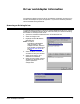
Driver Installation Driver Installation After you have extracted the driver files (if needed), follow these steps: 1. Open the Control Panel and double-click the Network icon, or right-click on the Network Neighborhood icon and select the Properties button. 2. Select the Adapters tab.
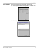
Driver Installation 3. Select the Add button. The list of supported network adapters appears: 4. Select the Have Disk button. 5. If you are installing the driver from a diskette, insert the diskette. Note: Make sure that you have extracted the files from the Comtrol media or any downloaded file from the ftp/web sites. 6. Enter the drive and directory path to the installation files, and select the OK button.
Driver Installation 8. Select the Next button when the Add Device Wizard appears and follow the onscreen instructions to configure the adapter type you installed in your system. You must install and configure at least one adapter at this time. If you are installing more than one adapter, install all PCI-bus adapters before installing any ISA-bus adapters. Depending on the model of adapter you have installed, enter the following information.
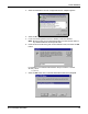
Driver Installation 9. When you have finished entering adapter configuration information, select the Finish button. The appropriate Device Setup tab appears: RocketPort PCI Example 10. Review the information shown. If desired, you can enter a more descriptive name for the adapter, change the base I/O address setting (ISA-bus only), or change the COM number assigned to the first port on the adapter. 11. Select the OK button to save the device configuration. The Main Setup tab appears: 12.
Driver Installation Note: If you are installing more than one adapter, install all PCI-bus adapters before installing any ISA-bus adapters. 13. If you have installed a RocketPort adapter that is capable of speeds over 230.4K bps, you can configure the driver for high-speed operation at this time. Follow these steps: a. Select the Options tab. b. Use the Scan Rate droplist to select a driver servicing rate. For example, to use an Octacable at 460.8K bps, select 4. To use a RocketPort Plus at 921.
Verifying Installation Verifying Installation After you shut down and restart the server, access the Windows NT Administrative Tools menu and open the Event Viewer. If the installation was successful, there is an “i” type log entry stating that the driver successfully initialized the hardware. If the installation failed, there is a stop or “!” type event log entry. Doubleclick on the log entry for more information. If the Verbose Event Log option is enabled, additional details may be listed.
Changing or Viewing Driver Configuration Changing or Viewing Driver Configuration To view or change the driver configuration after installation, follow these steps: 1. Use one of these methods to start the Comtrol Setup program: a. From the RocketPort/RocketModem program group, double-click on the RocketPort Setup icon. b. From the Start button menu, select Programs, then Comtrol RocketPort/ RocketModem, then RocketPort Setup command. c.
Changing or Viewing Driver Configuration 3. Select, clear, or set the following as desired: a. Verbose Event Log. Select this check box to cause longer messages to be sent to the Windows NT Event Log. This added information can be useful when debugging communications and configuration problems. b. Scan Rate. Use this droplist to set the driver servicing rate. As a general rule this is changed only if you are driving ports at rates in excess of 230.4 Kbps.
Changing or Viewing Adapter Configuration Changing or Viewing Adapter Configuration To view or change adapter configuration after installation, follow these steps: 1. Start the Comtrol Setup program. The Main Setup tab appears: 2. In the Configuration list, select on the adapter you want to work with and select the Properties button. Note: The Summary group displays the basic device configuration, as entered using the Add Device Wizard.
Changing or Viewing Adapter Configuration b. Base I/O Address. (ISA-bus adapters only.) If desired, use the droplist to select a different base I/O address. If this is the first ISA-bus adapter in the system, the I/O address DIP switch setting on the adapter must match the DIP switch illustration shown to the right of the entry field. If this is the second or subsequent ISA-bus adapter, you may select any available I/O address range.
Changing or Viewing Port Configuration Changing or Viewing Port Configuration To view or change individual port configuration, follow these steps: 1. Start the Setup program. The Main Setup tab appears: 2. If necessary, click the [+] button in front of the adapter name so that the ports on the adapter are displayed. Note: To hide the list of ports, click the [-] button in front of the adapter name. 3. In the Configuration list, select the port you want to work with. Then select the Properties button.
General Port Setup Note: The tabs and options present in this window depend on the adapter model and driver options selected. 4. View or change the port properties as desired. For reference, see the following discussions. When you are done, select the OK button to close the Port Setup tab and return to the Main Setup tab. If you have selected the Clone check box, the changes you make are applied to all Comtrol ports controlled by this driver.
RS-485 Tab RS-485 Tab This tab appears if RS-485 is enabled in the driver Options tab. Use it to enable and configure RS-485 on specific ports. If you want to use RS-485, you must have: • hardware that supports RS-485, and • RS-485 enabled on the Options tab and the individual port. Override and lock to RS-485 toggle mode Select this check box to switch the selected port to RS-485 mode. RS-485 Toggle RTS Low Select this check box to toggle the RTS output signal low during data transmission.
Adding an Adapter Adding an Adapter To add adapters to an existing installation, follow these steps: 1. Shut down the server, switch off the power, and remove the cover. 2. If you are installing an ISA-bus adapter, set the I/O address DIP switches as indicated in the hardware installation instructions. 3. Install the new adapter in an available slot of the correct bus type. 4. Replace the cover and power up the server. 5. Start Windows NT and log in as the system administrator. 6. Start the Setup program.
Windows NT Configuration Overview Configuring Modems After installing the hardware and driver for Windows NT, you can use this discussion to configure modem COM ports. The Comtrol device can support any asynchronous serial modem for use by any application that uses TAPI. For information regarding port pinouts and signals, see Locating Hardware Installation Documentation on Page 5.
Installing Modems 5. Check the “Don’t detect my modem...” box and select the Next button. Note: While Windows NT can automatically detect modems, we advise against using this option as auto-detect feature may cause some multiprocessor systems to lock up, and the modems may be installed in reverse order. 6. Select the appropriate manufacturer and model and selec the OK button.
Further Modem Configuration 8. Select the Finish button. The modem software is installed on the selected ports. Depending on prior configuration, you may be asked to enter your country of use, area code, the number you dial to get an outside line, and whether you have tone or pulse dialing at this time. 9. If you need to configure modem properties (maximum baud rate, data bits, parity, and so on), select the Properties button, make the needed changes, then select OK to return to this window.
Installing and Configuring RAS Installing and Configuring RAS After installing the hardware and driver, and installing and configuring at least one RAS device (for example, a modem), use this section to install and configure Remote Access Service (RAS).
Adding or Reconfiguring a RAS Device 4. Enter the location of the Windows NT files (for example, d:\i386) and select the Continue button. The appropriate files are copied onto your hard drive. The RAS installation process automatically launches the Add RAS Device process. Go to Adding or Reconfiguring a RAS Device, Step 5. Note: If you install or reinstall RAS from your original Windows NT 4.
Adding or Reconfiguring a RAS Device 4. To reconfigure an existing RAS port, highlight the port/device and select the Configure button. Then go to Step 7. 5. To add a new RAS device—for example, if you are configuring a new modem—select the Add button. The Add RAS Device window appears: 6. Use the droplist to select the COM port (modem) that you want to configure and select the OK button. Note: If no modems appear on this list, you need to install a modem, see Installing Modems.
Adding or Reconfiguring a RAS Device The Remote Access Setup window reappears. 9. Highlight the COM port (modem) again and select the Network button. 10. Select the appropriate dial out protocols, dial in protocols, logon security levels, enable multilink (if required) and select the OK button Note: Only previously configured protocols are selectable. If you want to set up a protocol that is grayed out, you must first add it using the Network Protocols tab.
Adding or Reconfiguring a RAS Device 12. If you select TCP/IP, the following window appears. Make the appropriate selections for your environment and press the OK button. 13. If you select IPX, the following window appears. Make the appropriate selection for your environment and select the OK button. 14. Select the OK button to exit the Network Configuration window and return to the Remote Access Setup window. Note: Choices made during network configuration will effect the entire system. 15.
Configuring Printers Configuring Printers Use this subsection to configure printers for the Comtrol device after installing the hardware and driver. Adding Serial Printers Follow these steps to configure a serial printer in Windows NT: 1. Connect the printer to the desired port. Use a DTE-to-DTE null modem cable unless the printer maker specifies otherwise. 2. Open the Printers control panel and double-click on the Add Printer icon. 3. Select the My Computer check box, then the Next button. 4.
Adding Serial Printers the \\.\ prefix. For example, to reference COM12, enter \\.\COM12: (make sure that you add the colon) d. Select the OK button. e. Select the Close button to return to the Add Printer Wizard. f. Select the Next button. 6. Select the printer make and model and select the Next button. If your printer is not on the make and model lists, but you have a manufacturer-supplied printer diskette, select the Have Disk button.
Changing Printer Port Configuration also be required to insert the operating system media so that Windows NT can extract the necessary driver files.) 10. Select whether to print a test page and select the Finish button. You are now ready to begin using the printer. No reboot is needed. Changing Printer Port Configuration If the printer does not successfully print the test page, it may be necessary to change the port baud rate, parity, and so on.
Comtrol Tools This section discusses the following utilities that are installed with most Comtrol drivers for Microsoft operating systems: • Test Terminal program (wcom32.exe), which can be used to troubleshoot communications on a port-by-port basis (Using Test Terminal on Page 34). • Port Monitor program (portmon.exe), which checks for errors, modem control, and status signals (Using Port Monitor on Page 37). In addition, it provides you with raw byte input and output counts.
Testing a Comtrol Device 4. Select the COM port you want to test. If the COM port does not exist or if it is currently being used by another program, a Create File Error message appears. If the COM port is available, a terminal window appears: Note: Notice the button in the terminal window. If this option is activated, it is green and uppercase ( ), the COM port internal loopback feature is activated, and the data is returned by the COM port hardware.
Testing a Comtrol Device (RS-485) 3. If further testing is required, select Loopback Test from the Port menu. If the loopback plug is in place and the port is working correctly, the system should return the message Passed. If the loopback plug is not in place or the port is not working correctly, the system will return the message Failed. Testing a Comtrol Device (RS-485) Perform the following procedure to determine if a port or ports are functioning properly. 1.
Using Port Monitor Using Port Monitor The Port Monitor program (portmon.exe) offers a summary of all Comtrol device statistics in one spreadsheet view. It also enables you to verify operation of all Comtrol device ports from a single window. The Port Monitor display follows the familiar spreadsheet model: each COM port is a horizontal row, and each vertical column displays a variable or value for the respective COM port. For definitions of the abbreviations used, see Port Monitor Variables on Page 41.
Changing Screen Appearance Once the monitor window appears, Port Monitor is active and collecting data. If any cumulative data has been saved from previous sessions, it is automatically brought in and used. Port Monitor continues to run and collect data until you terminate it, at which point all accumulated data is automatically saved for use in the next session. Changing Screen Appearance While Port Monitor is running, there are a number of commands and controls that change the appearance of the screen.
Column Setup Column Setup Report Configuration When you select Add or Properties from the column shortcut menu, the Column Setup window appears: • Use the Input droplist to select the variable displayed in the column. • Use the Type droplist to select the way in which the value displays: either as an integer, as an on/off state, as an integer with a kilo, mega, or giga suffix, or as an hh:mm:ss time stamp. This defaults to the appropriate type for the selected Input variable.
Port Monitor Files executed after the daily reports have been generated. The Update Time option allows you to set the rate at which the port information is obtained and the calculations performed. There is a trade-off between Port Monitor efficiency and response time. If you are using Port Monitor to view the port activity on the screen, you may want to set the update time to 1 or 2 seconds, so that the screen is updated frequently.
Port Monitor Variables Port Monitor Variables The following table lists Port Monitor variables. Variable Comtrol Tools Description Open Open status, on if open, off if closed. Cts Input CTS pin status. Dsr Input DSR pin status. Cd Input CD (carrier detect) pin status. Rts Output RTS pin status. Dtr Output DTR pin status. TxTotal Total bytes transmitted. RxTotal Total bytes received. TxCPSInst Instantaneous average of transmit characters per second.
Using Peer Tracer Variable TxCPSMinAvMaxWrk Description Peak TxCPSInst for the current minute. TxCPSHourAvMaxWrk Peak TxMinCPS for the current hour. TxCPSDayAvMaxWrk Peak TxHourCPS for the current day. RxCPSMinAvMaxWrk Peak RxCPSInst for the current minute. RxCPSHourAvMaxWrk Peak RxMinCPS for the current hour. RxCPSDayAvMaxWrk Peak RxHourCPS for the current day. CDRuns Carrier detect turn-on count. CDDayRuns Carrier detect turn-on count in the last day.
Starting Peer Starting Peer Peer Tracer does not appear in most Comtrol program groups and you may need to start the application from the Windows Explorer. Use the table below to determine whether you can start Peer from a program group or where to locate the executable. Product Operating System Starting Peer DeviceMaster RTS, Windows NT, RocketPort Serial Hub ia, Windows 2000, RocketPort Serial Hub Si Windows XP \WINNT\system32\rpshSi\peer.
Troubleshooting and Technical Support This section contains troubleshooting information for your Comtrol device. You should review the following subsections before calling Technical Support because they will request that you perform many of the procedures or verifications before they will be able to help you diagnose the problem. Troubleshooting If you are having trouble with a RocketPort or RocketModem, try the following.
Device Driver and OS Capabilities and Limitations 11. If you are using a PCI-bus adapter, check the Summary in the Device Setup window to verify that the correct bus type was selected during installation. 12. Use the Main Setup Options to reset the Scan Rate to 10 ms. 13. Remove the driver and reinstall it, using a different I/O address (ISA-bus adapters only). 14. If your RocketModem model supports the reset function, use the Reset function (page 21) to reset the modem to its default (power-on) state. 15.
Before calling Technical Support Device Control Block Settings XonChar, XoffChar Status Supported Unsupported IOCTL Functionality Status IOCTL_SERIAL_XOFF_COUN Not supported TER IOCTL_SERIAL_SET_HANDF SERIAL_DSR_HANDSHAKE, LOW SERIAL_DCD_HANDSHAKE, (unsupported options) SERIAL_DSR_SENSITIVITY IOCTL_SERIAL_GET_COMM STATUS (unsupported options) Before calling Technical Support fDsrHold, fRlsdHold Comtrol has a staff of support technicians available to help you.
Technical Support Technical Support If you need technical support, contact Comtrol using one of the following methods. Contact Method Corporate Headquarters Comtrol Europe FAQ/Online http://support.comtrol.com/support.asp Downloads http://support.comtrol.com/download.asp Email support@comtrol.com support@comtrol.co.uk Web site http://www.comtrol.com http://www.comtrol.co.
Index A Adapters tab 7, 9 Add Device Wizard 22 Add Printer Wizard 31, 32 Add RAS Device 27 adding an adapter 22 serial printers 31 administrative rights 26 B base I/O address 18 baud rate 20 buffer 20 C capabilities 45 changing adapter configuration 17 port configuration 19 printer port assignment 33 printer port configuration 33 clone 20, 30 COM port 18 COM Properties 19 Comtrol on-line support 46 configuration list 17 Configure Port Usage 28 configuring modems 23 printers 31 RAS 26 customer support on-lin
override baud rate 20 P phone 47 physical transmission 20 port monitor commands 38 files 40 program 37 port numbering diagram 44 Port Setup tab 20 Ports tab 33 R RAS 26 receive calls only 28 reconfigure RAS device 27 Remote Access Setup 28, 29 removing an adapter 22 an existing driver 7 reports 37 reset 21 ring indicator signal 20 RS-485 converter 14 tab 21 toggle mode 21 RTS output signal 21 S scan rate 13, 16, 20 service packs 6 Services tab 26 servicing rate 16 starting COM port 18 status signals 37 summ