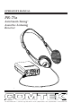
OPERATOR’S MANUAL PR-75a AutoSmart-Tuning Assistive Listening Receiver TM 357 West 2700 South • Salt Lake City, Utah 84115 • Phone: (800) 496-3463 • Fax: (801) 484-6906 • www.comtek.
TABLE OF CONTENTS Introduction ........................................................... 1 Controls and Indicators ............................................... 2 Setup and Operation 3-4 ....................................................... Optional Accessories ............................................ 5 Frequency Information .......................................... 6-7 Battery Information ............................................... 8-9 Belt Clip Removal and Installation .......
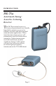
INTRODUCTION PR-75a AutoSmart-Tuning Assistive Listening Receiver TM T he PR-75a personal receiver is the newest generation of user-friendly, high fidelity monitor receivers for auditory assistance and other personal communication applications. When turned on, this unique receiver will automatically tune itself to the closest transmitter.
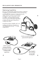
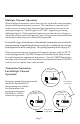
PR-75a CONTROLS AND INDICATORS PR-75a Controls n BATTERY COMPARTMENT: The battery compartment features a hinged battery cover and a polarity protection design to ensure that only proper battery polarity can occur. o AUDIO OUTPUT JACK: This mono audio output jack accommodates any low impedance mono or stereo headphone; also functions as automatic on/off power switch when headphone is plugged in and also as rechargeable battery charging access.
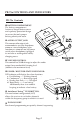
PR-75a SETUP AND OPERATION Setup a. Open the battery door on the receiver (see page 8) and insert two 1.5 V AA alkaline batteries (Eveready E91 or equivalent). This type of battery will offer up to 100 hours of operation. If a rechargeable battery is to be used, ensure that it has been allowed to charge at least twelve hours to bring it to full charge (see page 9 for battery charger instructions). The use of carbon batteries is not recommended. b.
PR-75a SETUP AND OPERATION Monitoring Capabilities Because each monitoring application requires a different headphone or transducer to best satisfy each listening need, the PR-75a can source a strong mono audio signal (200 mW) to either stereo or mono headphones with an impedance as low as 16 ohm. A hearing aid type button receiver may be used with an impedance as high as 2k ohm and still produce a strong audio signal.
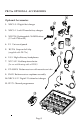
PR-75a OPTIONAL ACCESSORIES Optional Accessories 1. NBC 9-3-1 Digital fast charger 2. NBC 3-1 3 volt 12 hour battery charger 3. NH 1700 Rechargeable Ni-MH battery (1.2 volt 1700 mAh) 4. P-1 Universal pouch 5. BC-216 Snap-on belt clip (supplied with PR-75a) 6. LS-3 High efficiency headphones 7. NTC-102 Neckloop transductor (for use with hearing aids or IR230) 8. ET-4 SM-N Button receiver with acoustic ear tube 9. SM-N Button receiver earphone assembly 10. NBC 9-3-12 Digital 12 station fast charger 11.
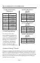
PR-75a FREQUENCY INFORMATION 72 MHz WIDE-BAND CHANNELS GROUP FREQUENCY CHART GROUP 1 CHANNEL FREQUENCY CHANNEL FREQUENCY A B C D E F G H I J 72.100 MHz 72.300 MHz 72.500 MHz 72.700 MHz 72.900 MHz 75.500 MHz 75.700 MHz 75.900 MHz 74.700 MHz 75.300 MHz A E H J 72.100 MHz 72.900 MHz 75.900 MHz 75.300 MHz GROUP FREQUENCY CHART GROUP 2 Custom Programming The Data I/O port allows special channel programming with the FP-75 programmer to create new dedicated frequency groups.
Multiple Channel Operation When multiple transmitters (more than two) are used in the same proximity, intermodulation interference can occur. This condition is common to all radio receivers to some extent when multiple transmitters are used in the same operating area. The RF signals will “MIX” together generating additional signals.
PR-75a BATTERY INFORMATION Low Battery Indicator The LED indicator on the PR-75a is a multi-function indicator which includes low battery detection. When the receiver is operating normally, the LED indicator illuminates continuously indicating that the receiver is receiving a signal on the tuned channel. If the battery is low, the LED will show a rapid flash indicating the battery is low.
Battery Charging 1. Make sure that two AA size 1.2 volt Ni-MH rechargeable cells are used with a minimum of 1400 mAh capacity. (Alkaline batteries must not be charged.) TANT IMPOR 2. Note that the red charging indicator on the charger is “ON” when the PR-75a is plugged into the charger through the audio output jack. 3. When using the NBC 3-1 charger allow the battery to charge for 12 hours for a full charge. The unit must then be unplugged.
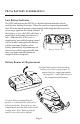
PR-75a SNAP-ON BELT CLIP Belt clip removal indent Belt clip removal Flex out and pull down with your thumb or a large coin (quarter) to unsnap belt clip from case. STEP 2: Rotate belt clip down onto case. Apply pressure on both sides of clip, snapping clip retainers into slots. Belt clip installation Clip retainer STEP 1: Hook belt clip retaining lip over front case ridge.
PR-75a SPECIFICATIONS Audio Output: Headset output 200 mW average (Impedance as low as 16 ohm) Frequency Stability: 0.002% frequency synthesized crystal controlled Connectors: • Mono 3.5 mm audio output connector and charging input. • 2.5 mm connector for I/O data programming. RF Sensitivity: 1.3 µV for 38 dB of quieting (average) Indicators: Multi-function LED a. Channel-seeking b. Received signal c. No signal d.
PR-75a WARRANTY AND SERVICE Warranty COMTEK transmitters and receivers are warranted to be free from defects in workmanship and material under normal stand-alone use and conditions for a period of two years from date of original purchase. Items such as headphones and earphones, neckloops, and cords are warranted to be free from defects in workmanship and material for a period of 90 days from the date of original purchase. Batteries are not covered by this warranty.
357 West 2700 South • Salt Lake City, Utah 84115 • Phone: (800) 496-3463 • Fax: (801) 484-6906 • www.comtek.