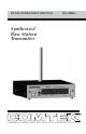
BST-25 OPERATOR’S MANUAL (216 MHz) Synthesized Base Station Transmitter 357 West 2700 South • Salt Lake City, Utah 84115 • Phone: (800) 496-3463 • Fax: (801) 484-6906 • http://www.comtek.
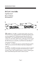
INTRODUCTION BST-25 / 216 MHz Synthesized Base Station Transmitter T he BST-25 / 216 MHz is a professional quality, low power, auxiliary base station transmitter designed to operate in the newly assigned 216-217 MHz band under part 95 of the FCC regulations. This transmitter may be used for personal cueing, for tour guide applications, language interpretation, and for assistive listening. For highest fidelity operation, the PR-216 receiver must be used with the wide-band companded channels.
OPERATING INSTRUCTIONS Equipment Placement If the BST-25 base station is to be rack-mounted, a remote antenna must be used. The base station should be mounted away from equipment that uses large power transformers to reduce 60 Hz hum possibilities. If the base station is to be used outside of a traditional rackmounted environment, the screw-in whip antenna should be free of any metallic objects when fully extended (12 1/2 inches).
Power Requirements The BST-25 base station is designed to be powered by 12 volts DC. A power adaptor is furnished for use with standard 110V AC. The on/off switch on the front panel of the base station turns on the transmitter. Audio Input Connections The base station transmitter has facilities for audio input from a mic, line, or speaker level source. The mic/line level audio input is a transformer balanced input and requires a standard XLR-3 male connector.
OPERATING INSTRUCTIONS (continued) d. Plug the adaptor into a standard AC outlet and plug the power connector into the DC input jack of the transmitter. Turn the display switch on the front of the transmitter "ON" to allow monitoring of the transmitter frequency. Turn the main power switch on the front of the base station to the "ON" position. The front display should now be illuminated. e.
a. Ensure that the audio source has been optimized for best signal-to-noise ratio. b. The “MIC/LINE” switch located at the back of the transmitter should be switched to the appropriate setting: "MIC" for mic level or weak line level input; “LINE” level for line level input. c.
OPERATING INSTRUCTIONS (continued) To avoid this type of interference, select frequencies from one of the standard groups (see frequency group charts on page 11), or use COMTEK’s frequency selection guide software to determine appropriate frequencies. (Contact COMTEK to obtain a free copy of the frequency selection software.) Test Tone The BST-25 base station transmitter has an internal 400 Hz source which is transmitted when the “TONE” switch is enabled.
Display On and Off The digital display can be turned on or off using the “DISPLAY” switch. Disabling the display reduces the current consumption of the transmitter for battery operation. In environments where the display could be distracting, disabling the display may also be appropriate. When the display is disabled, the tuning controls are also disabled, ensuring the transmitter frequency is not changed inadvertently. With the display disabled, one segment is turned on as a power indicator.
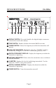
BST-25 FRONT PANEL 1 2 3 (216 MHz) 4 5 6 7 8 9 1 DISPLAY SWITCH: This switch disables the digital display to conserve current when used with a battery. 2 TONE SWITCH: Enables/disables the internal 400 Hz test tone. 3 TUNING SWITCH: Selects the frequency on which the transmitter will operate. 4 LOCK OUT INDICATOR: Illuminates when the “TUNING” switch is disabled by setting the “LOCK OUT” switch (rear panel) to “ON”.
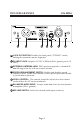
BST-25 REAR PANEL 10 11 (216 MHz) 12 13 14 15 16 10 LOCK OUT SWITCH: Disables the (front panel) “TUNING” switch, locking the transmitter on one frequency. 11 DC INPUT JACK: Requires 12 VDC at 500 mA (Pin-1 ground, pin-4 +12 volts). 12 EXTERNAL ANTENNA JACK: BNC connector provides a standard 50 ohm RF output for use with an external antenna. 13 SPEECH ENHANCEMENT SWITCH: Enables and disables speech enhance feature.
BST-25 216 MHz FREQUENCY CHART CHANNEL FREQUENCY NARROW-BAND CHANNELS For use with COMTEK and other manufacturers CHANNEL FREQUENCY 32 216.7875 MHz 1 216.0125 MHz 33 216.8125 MHz 2 216.0375 MHz 34 216.8375 MHz 3 216.0625 MHz 35 216.8625 MHz 4 216.0875 MHz 36 216.8875 MHz 5 216.1125 MHz 37 216.9125 MHz 6 216.1375 MHz 38 216.9375 MHz 7 216.1625 MHz 39 216.9625 MHz 8 216.1875 MHz 40 216.9875 MHz WIDE-BAND CHANNELS For use with COMTEK equipment only 9 216.
BST-25 BST-25 216 MHz NARROW-BAND FREQUENCY GROUPS 216 MHz WIDE-BAND FREQUENCY GROUPS Compatible with COMTEK and other manufacturers (5 kHz deviation) For COMTEK equipment only (10 kHz deviation) GROUP 1 GROUP A CHANNEL FREQUENCY CHANNEL FREQUENCY 1 9 15 24 31 36 216.0125 MHz 216.2125 MHz 216.3625 MHz 216.5875 MHz 216.7625 MHz 216.8875 MHz 41 44 51 55 60 216.0250 MHz 216.1750 MHz 216.5250 MHz 216.7250 MHz 216.
BST-25 INTERNAL ADJUSTMENTS (216 MHz) NOTE: The Compand Switch must be set to the “ON” position for automatic companded and non-companded operation with channel selection. The “OFF” position is only used for testing.
BST-25 ACCESSORIES (216 MHz) Included Accessories 1. C-16 Carrying case 2. BST-25 Operator’s manual 3. TWA-72 Whip antenna 4. BST-25 Base station transmitter 5.
BST-25 ACCESSORIES (216 MHz) Optional Accessories 1. RDA-2 Remote dipole antenna 2. PRA Phase-Right coaxial antenna 3. MO-1/4 wave vehicle installation antenna or MO-1/4 wave magnetic mount antenna 4. PRA Phase-Right antenna mount 5. RMK 25 Single rack-mount face plate 6.
BST-25 SPECIFICATIONS Audio Inputs: • Mic XLR, 600 ohm Balanced -40 dBV (nominal) • Line XLR, 10 k ohm Balanced 0 dBV (nominal) Connectors: • XLR-3 Female audio input connector for mic and line input • XLR-4 Male power input 12 volts • BNC type RF output connector Operation Indicators: • LED Bargraph VU Meter displays audio input (modulation) • Two-Digit Alpha Numeric Display shows operating channel • Five-Digit Numeric Display shows operating frequency • Antenna Indicator displays deficient antenna condit
WARRANTY COMTEK warrants this product to be free from defects in workmanship and material under normal use and conditions for a period of one year from date of original purchase. Items such as batteries, neckloops, and cords are not covered by the warranty. Damage due to misuse, ill treatment and unauthorized modification and repairs are not covered by this warranty. COMTEK is not liable for consequential damages arising out of any failure of the equipment to perform as intended.
357 West 2700 South • Salt Lake City, Utah 84115 • Phone: (800) 496-3463 • Fax: (801) 484-6906 • http://www.comtek.