
Manual

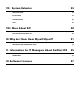


Table Of Contents

7
III. Setting Up EarShot IFB
Hardware Attachments and Connections
The figure below shows the rear panel of the EarShot IFB mainframe:
1 2 3 4 5 6
7 8 9 10
11 12
ANALOG
AES3
VGASECPRIUSB SERIAL
GPIO
1 Mains Power - Apply universal mains power (110-240VAC) to the IEC connector here.
2 ANALOG/AES3 Input Switch - This switch determines whether the leftmost XLR connector is
used for analog FEED/IFB1 audio to callers, or is configured as an AES3 digital audio input.
3 FEED/IFB 1 INPUT - In analog mode, this XLR connector should be sent a balanced, 0dBu
signal that is heard by callers when they select FEED 1, or alternately (if this input is configured
as IFB 1), when IFB 1 is active. In digital AES3 mode, both FEED/IFB 1 INPUT and FEED/IFB 2
INPUT are applied here (on left and right channel, respectively).
4 FEED/IFB 2 INPUT - This XLR connector should be sent a balanced, 0dBu signal that is heard
by callers when they select FEED 2, or alternately (if this input is configured as IFB 2), on a
different feed when IFB 2 is active. This input is disabled when in AES3 mode.
5 FEED 3 INPUT - This XLR connector should be sent a balanced, 0dBu signal that is heard by
callers when they select FEED 3.
6 FEED 4 INPUT - This XLR connector should be sent a balanced, 0dBu signal that is heard by
callers when they select FEED 4.
7 USB (x2) -Connect a keyboard and mouse to these ports to utilize the Console IP Setup
Interface.
8 Primary Ethernet Port - Connect your network to this gigabit compatible Ethernet port.
9 Secondary Ethernet Port - If you choose, you can run VoIP services on two different Ethernet
networks on Earshot. A typical use case would be to use the primary Ethernet port to connect
to a cloud-based VoIP provider, and the secondary port to connect to a PBX or gateway
device on a LAN that can’t connect to the Internet. Note: the secondary Ethernet port offers
only static addressing.
10 Contact Closure Connector - This contains 4 contact closure input and output signals, for
various remote control and tally functions as described further on.
11 Serial Port - This is an RS-232 connector that presents a serial port for future use.
12 VGA - Computer video port. Attach a monitor here for Console IP Setup Interface.