Product Manual
ACCESS NX Portable Manual I. Introduction 10 Unpacking and Checking Contents 10 About ACCESS NX Portable 10 About Comrex 11 Warranty and Disclaimer 11 II. Controls and Connections 12 Figure 1 Front Panel Diagram and descriptions 12 Figure 2 top panel diagram and descriptions 13 Figure 3 SIDE PANEL DIAGRAM AND DESCRIPTIONS 14 Figure 4 rear panel diagram and descriptions 15 MONO VS. STEREO 15 III. NX Portable Quick Start 16 IV. Introduction to crosslock 18 V.
VII. Making Connections with NX (Remote Connections screen) 27 Connections with Switchboard 27 Manual Connections without CrossLock (legacy BRIC-Normal mode) 28 Manual Connections with CrossLock 29 Outgoing calls 29 Incoming Calls 29 VIII. network manager 30 Ethernet 30 Wi-Fi 31 3G/4G 32 POTS 32 IX. web browser 33 X. dashboard 34 XI.
XII. Statistics Menus 38 CrossLock Stats 38 Remote statistics 39 channel statistics 40 XIII. Profile Manager Menu 41 Default Profile 42 Viewing Profile details 42 Editing and Adding profiles 44 XIV. system settings Menu 45 contact closure settings 47 security settings 48 Switchboard Settings 49 Alternate Modes 50 BRIC Normal Settings 50 Modem 50 EBU 3326/SIP 50 XV. Crosslock menu 51 XVI. User Settings Menu 52 XVII.
XVIII. ABOUT THE ALGORITHMS 56 OPUS 56 LINEAR PCM 56 FLAC 56 G.722 57 AAC 57 HE-AAC 57 HE-AACV2 57 AAC-LD 57 AAC-ELD 57 XIX. Switchboard Traversal Server (TS) 60 Configuring Switchboard 60 Logging In And Setting Up Switchboard 60 Creating Users 61 Contact Lists 62 Shares 64 managing multiple contact lists 65 bulk actions for contact lists 67 Switchboard Theory and Concepts 69 XX.
Using Device Manager 77 XXII. ToolBox 80 LoCatIons 81 Configuring Wi-Fi 81 Advanced Network settIngs in toolbox 83 XXIII. OPERATING NX IN A 24/7 ENVIRONMENT 84 Setting NX For 24/7 Operation XXIV.
XXVI. IP MULTICAST 94 Multicast Profiles 94 Setting Up A Multicast Remote 95 Time-To-Live 95 Changing Port Numbers For Multicast 95 XXVII. STREAMING SERVER FUNCTION 96 Decoding An HTTP Stream 96 Simultaneously Connecting NX And Streaming 96 XXVIII. POTS (PLAIN OLD TELEPHONE SERVICE) CODEC CONNECTIONS 97 POTS Codec Set-Up For NX Compatibility 97 Using NX With POTS 97 Rate Vs. Retrain 98 TROUBLESHOOTING POTS CONNECTION 99 XXIX.
Advanced System Settings 109 Auxiliary Serial 109 Connections 110 Security 110 Switchboard Server 111 BRIC Normal Settings 112 EBU 3326/SIP Settings 113 HTTP Settings 115 Modem Settings 116 Standard RTP Settings 117 TCP Settings 118 CrossLock settIngs 119 hotswap 122 XXXI. Advanced 3G/4G Network settings 126 XXXIi. LICENSE AND WARRANTY DISCLOSURES FOR COMREX ACCESS NX 127 LICENSES 127 WARRANTY 128 XXXiII.
DECODE SIDE SETTINGS ONLY 134 ENCODE SIDE SETTINGS ONLY 134 FULL-TIME OR TRIGGERED CONNECTIONS 134 APPENDIX D - USING COMREX ACCESS DECODER DOWNMIX 135 APPENDIX E - SPECIFICATIONS 137 CONNECTIONS 137 AUDIO SPECIFICATIONS 137 POWER 137 PHYSICAL 137 APPENDIX F - CONNECTIONS TO MULTIRACK 138 BRIC NORMAL CONNECTIONS 138 MANUAL CROSSLOCK CONNECTIONS 138 MAKING CONNECTIONS WITH SWITCHBOARD 139 APPENDIX G - HTML5 Web Interface 140 Login 140 Interface Page Sections 140 Connecti
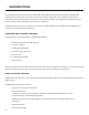
I. Introduction Congratulations on purchasing the Comrex ACCESS NX codec system with CrossLock technology. Since ACCESS was introduced over a decade ago, it has become the world’s leading IP audio codec. And in that time, IP transmission technology has developed significantly. We’ve taken our world-class platform, along with the last decade of technical growth, and built a brand new platform for the future—ACCESS NX.
About Comrex Comrex has been building reliable, high quality broadcast equipment since 1961. Our products are used daily in every part of the world by networks, stations and program producers. Every product we manufacture has been carefully designed to function flawlessly, under the harshest conditions, over many years of use. Each unit we ship has been individually and thoroughly tested. Comrex stands behind its products.
II. Controls and Connections Figure 1 Front Panel Diagram and descriptions 1 DISPLAY - Touchscreen display. This is where you initialize your broadcast from the NX to the studio unit (typically an ACCESS Rackmount), view and edit settings, and monitor connections. 2, 5 CH1 and CH2 LOCAL OUTPUT control knob - Adjusts the level of local audio to the corresponding headphone jack. 3, 6 CH1 and CH2 REMOTE OUTPUT control knob - Adjusts the level of remote audio to the corresponding headphone jack.
Figure 2 top panel diagram and descriptions 1, 2 USB HOST PORTS - These ports are for connections to the included USB Wi-Fi adapter, Comrex Connect Modems, compatible USB 3G/4G devices and the optional POTS modem. To learn how to use two networks simultaneously, go to the CrossLock Details section on page 73 for details. NOTE: Not all 3G/4G modems are compatible. Check our website for compatible modems at http://www.comrex.com/products/compatible-3g4g-modems or contact techies@comrex.
IMPORTANT: Make careful note of the direction you are plugging the power into the connector. The arrow on the connector should be facing down when connecting to the NX. The same applies to the Serial cable. The Contact Closure cable will have the flat section facing down. Figure 3 SIDE PANEL DIAGRAM AND DESCRIPTIONS 1 MIC/LINE IN - 3-pin female XLR connectors designed to accept a balanced, microphone or line level audio feed.
Figure 4 rear panel diagram and descriptions 1 BATTERY COMPARTMENT - This internal battery compartment holds the supplied Lithium-ion battery. 2 ADJUSTABLE STRAP - Use this padded adjustable strap to carry the unit. 3 MIXER PORT - This connector is for docking to the optional 4 channel NX Mixer. MONO VS. STEREO Because NX can encode and/or decode in stereo and mono modes, it’s important to understand how the audio inputs and outputs are handled in each mode.
III. A simple NX remote broadcast In this example, we will show you how to set up a simple broadcast with an NX in a remote location using a compatible 4G Verizon adapter. As shown below, the reporter has a microphone connected to the MIC/LINE IN XLR connector. Headphones are connected to the Headphone output. The Verizon adapter is plugged into the USB port on the top of the NX.
With the device powered on, verify Internet connectivity with the Verizon modem. On the NX display in the bottom status bar, any connected network will be displayed. Click on the 4G device listed, and an IP address will appear if you are successfully connected to the network. Let’s assume your codec fleet has an account on the Comrex Switchboard server (explained in the Introduction to Switchboard section on Page 19), and both ends of your connection are properly registered with it in advance.
IV. Introduction to crosslock CrossLock is an enhanced reliability layer that can be added to links made between Comrex codecs. CrossLock is optional but recommended, and is available in all Comrex codecs running firmware 4.0 and higher. In the case of connecting to Comrex codecs with earlier firmware, CrossLock is not used. Because CrossLock creates a VPN, it has its own rules. It can decide whether or not to resend information based on error correction.
V. Introduction to switchboard Switchboard is a feature that allows codecs to “sync” with a cloud-based server. Switchboard allows for easy connections to be made between codecs without any knowledge of IP addresses on both ends of the link. It also provides presence and status information about all the Comrex codecs in your fleet, and can help make some connections through routers and firewalls that might be difficult otherwise.
VII. getting started with NX Powering Up NX NX can be powered from its internal battery or an external supply. The internal battery has a low-voltage lockout function that prevents power-up if the battery voltage is too low. Whenever the external supply is attached, regardless of the whether NX is turned on or off, the internal battery will be charging. The battery status is always available by looking at the rear-panel battery LED (red = charging, green = full).
When a text entry is selected on the touchscreen, a virtual keyboard will automatically appear. The keyboard will close when you press enter, or select the close keyboard button in the bottom right. You can change the keyboard language by selecting the globe icon in the bottom left. When first booted, NX displays the “Remote Connections” screen as shown below. Remote Connections is one of the main screens available on NX, and is the default because connections are initiated and terminated from there.
The other main screens are selected by pressing the Menu icon on the upper left corner of the display. This will open a list of the options on the left side. The “Menu” key on the keypad mimics this. Whenever one of the main menus is chosen, options within that menu can be displayed by pressing the Options icon on the upper right side of the display. Pressing either the “Menu” or “Options” Icon again removes the slide-out list.
3 Remote Connections - Add, edit and delete connection destinations, show incoming connections, make outgoing connections, and check Switchboard status. 4 Dashboard - Designed to be active during a live feed, provides microphone mutes, control over contact closures, and shortcuts to other audio functions and levels. 5 Audio I/O - Configure the inputs for levels (Mic/Line), buss selection and mono/stereo. Adjust output levels and select sources for Line Out jack.
Each installed network has an icon that can be selected. Once selected, some basic network status will be displayed (e.g. Ethernet IP address), and a gear icon that will bring you to the configuration menu for that network when selected. The CrossLock icon will light green when a CrossLock connection is active. Once selected, a popup menu will provide CrossLock status and CrossLock delay settings.
The battery icon shows charging status or current level of the internal battery. Battery is always in charging state (or charged state) when the external supply is attached. If battery is disconnected, this icon will show an “X” over the icon. By selecting the battery icon, a popup menu showing the status and percentage of charge will appear.
The level meters show the current audio local input level (top) and the current return audio level (bottom). The meter is stereo, and mono sources reflect on both L&R channels. This is designed as a “peak” meter, and proper audio levels should remain below the right side of the meter. The help icon will open a window providing explanations relevant to the current menu item.
VII. Making Connections with NX (Remote Connections screen) NX connections are made via the Remote Connections option in the main menu. Besides giving you list of all possible outgoing connections and active incoming connections, the Remote Connections screen displays Switchboard status, showing whether your NX is currently synced to the Comrex Switchboard server.
The icon that appears next to the Switchboard member is color coded to show status: Green - Ready to accept call Yellow - Busy Red - Unable to accept call Gray - Offline If Switchboard determines that a CrossLock connection can be made, it will opt for that. If not, it will attempt a BRIC Normal connection.
Remote Name - Familiar name to call this entry. IP Address or Phone number - The public IP address of the destination (phone number for POTS calls). If using non-default ports, add the port number after a colon. Profile - Select which profile is used to make the connection. (Profiles determine encoders used and other parameters—see the Profile Manager Menu section on page 41.) If no selection is made for profiles, the call will proceed with the default profile of Opus mono.
IX. network manager On the left side of the Network Manager screen, NX presents a list of all network adapters (4G, Wi-Fi, etc.) that have been attached to NX, along with the internal Ethernet port. Note that with the CrossLock feature, it’s possible to have multiple active networks simultaneously. One important element of the Network Manager is the concept of Locations. A Location contains the settings specific to that network adapter for use on a specific network.
Selecting Configure here will open the configuration pop-up. For Ethernet, it’s recommended to leave the default network as-is (DHCP) for testing and upgrades, and to add static networks as additional Locations. To do this, select the arrow to the left of “Network Locations” to expand the Location list. You can then choose “Add Location”. You’ll then be able to select the new location, rename it, and apply the required information to use the Ethernet Port at the new location.
When you first attach the Wi-Fi adapter, you must enable it before using it or scanning with it. You can enable the Wi-Fi adapter by selecting it in the list and selecting Enable, or choose “Enabled” under the WLAN option and set it to “Yes”. NX allows you to “scan” for active Wi-Fi Access Points, much like a computer or smartphone. This is done via the “Locations” option under the WLAN adapter. Pressing “Scan” will deliver a list of active Wi-Fi networks.
X. web browser This option enables the built-in web browser in NX. The browser has all basic functions of your typical mobile browser, including SSL security and JavaScript. The browser is designed to be used on networks that require authorization (beyond Wi-Fi security). As an example, many hotels or retail stores redirect web users to a page, asking to accept terms or input passwords. Once a different screen is selected via the main menu, the browser stays in the background and keeps the last page open.
XI. dashboard The dashboard screen is designed to provide common functionality to the user when streaming live audio. The sections are: 1 Contact Closure triggers - In parallel with the physical contact closure connector, allows the sending of four end-to-end closure signals. 2 Remote Contact Closure status - Indicates the current state of the contact closure outputs (sent from the far end). 3 “All In” Mute - A toggle button to mute all the inputs to NX.
XII. Audio Inputs and outputs Audio Inputs NX has two adjustable mono audio input channels, and one fixed level stereo input. With the addition of the optional mixer, an additional four mono inputs are available. Each adjustable channel has a level indicator built into the input adjustment knob. The knob will light green (OK), yellow (hot), and red (limiting) on each channel. The audio input settings select the levels and destinations of each of these channels.
Mono/Stereo Rather than a pair of mono inputs (which get mixed into both channels of stereo encoders), pairs of input channels can be configured as L & R stereo. This is possible on the combination of channels 1 & 2, and (with the optional mixer attached) channels 3 & 4 and channels 5 & 6. Choosing the “Stereo” option on either of the inputs will set both inputs to this mode. In stereo mode, only the lower number channel has an active input level control.
AUDIO INputs Settings with mixer Audio Output Settings with mixer 37
XIII. Statistics Menus There are three different sections available on the Statistics menu: CrossLock; Remote; and Channel. The different graphs are available by scrolling left and right. When making a CrossLock connection, it is best to refer to the CrossLock stats to analyze performance. The Remote and Channel graphs are also available during a CrossLock connection because the legacy BRIC Normal protocol is still running while a CrossLock connection is active.
The top meter shows network utilization, showing data rate on an autoscaling graph. In the case of CrossLock connections using multiple networks (bonding or redundancy mode), the graph will be color-coded to show utilization of each network. Note that CrossLock has license to apportion data dynamically between networks, including making the choice not to use a network at all. This usually happens when CrossLock determines one network to have significantly lower delay and sufficient bandwidth.
channel statistics The Channel screen provides real-time graphs of outgoing and incoming packets. Each column represents one second of outgoing data, segmented into audio coding data (shown in blue) and overhead, such as IP/UDP headers, RTP headers and similar data (shown in light blue). The first screen shows you the rates in real-time. By swiping the screen to the left, it will show you an average of both Transmit Rate and Receive Rate.
XIV. Profile Manager Menu Profiles are what define the behavior and type of connection for your codecs in both directions. Profiles are separate from remotes, which define the destination to connect to. When using NX, the point where the connection originates controls all available connection parameters in both directions. Keep in mind that these profiles are useful only for connections initiated from the local ACCESS. Incoming connections are defined by the ACCESS at the other end.
Default Profile When a new remote connection is created (on the Remote Connections screen), a default profile is assigned unless a different profile is selected from the menu on the Remote Settings option on the Remote Connections menu. The default profile shows a D next to it in the list. OPUS Mono is the default profile when shipped from the factory. You can change the default profile by selecting it in the list and pressing the Set Default button.
Under the expanded profile, you will also see two additional folders named Local and Remote. You’ll use the Local Settings to determine how your NX behaves, and the Remote Settings will determine how the ACCESS on the far end behaves. The Local Settings and Remote Settings available are identical, so we will only cover the Local Settings. Connection Timeout - Under normal circumstances, a connection will be terminated on one end, and the other end will drop the connection.
Editing and Adding profiles Custom profiles are easy to create on NX. Simply select Add New Profile or highlight a profile already in the list and select Copy Profile. TIP: You cannot edit factory profiles. Comrex recommends that when creating a new profile, you copy a factory profile that is close to what you would like the settings to be, and edit that copied profile. Profile creation is segmented into commonly used and advanced options.
XV. system settings Menu System Settings define parameters that are not specific to a particular remote connection. Examples are how incoming (POTS and IP) calls are handled, global modem settings, and how the contact closures are assigned. Basic options are shown by default. Less used options are hidden until the Advanced option is selected. The System Settings Menu has the following categories: Connections; Contact Closures; Security; Switchboard Server; and Alternate Modes.
Connections settings Unit Name - Users are encouraged to name their codecs here. The default name of a codec is the unique MAC Address of the Ethernet port (Switchboard ID). When this is changed to something familiar and unique (such as “Roving reporter”, “Weather guy”, etc.
Always Connect To - This setting is available to designate a remote for “always-on” operation. This is useful in environments where a signal is required to be on 24 hours a day. To assign an “always-on” remote, pull down the menu and select which remote to designate as “always-on”. A connection will be made and sustained to the chosen remote. contact closure settings CC Connect Status - Alters the performance of output contact closure #4.
security settings Remote Control Password - Allows you to define a password for the webpage login screen and firmware updater. The default password is comrex (lowercase). You can disable the remote control and firmware updating functionality completely by disabling the Remote Control option. Remote Control - If this function is disabled, the unit will not serve any webpage from its IP address, and the firmware updater will not function.
Switchboard Settings Switchboard Enabled - Allows the use of the Switchboard Server to connect to remotes. Show Offline Units - When enabled, offline remotes will be shown in the Remotes list.
Alternate Modes BRIC Normal Settings Accept Incoming Connections - This determines if this NX is to be used for incoming normal IP connections. If this function is not enabled, NX will only support outgoing calls using BRIC Normal Mode. Modem Accept Incoming Connections - POTS calls must be answered automatically on NX. If this option is disabled, no POTS calls will be answered and only outgoing POTS connections can be made.
XVI. Crosslock menu These settings determine how the CrossLock reliability layer behaves. Most users should leave these settings as default. Enable - Allow CrossLock connections in general. Default is yes. Note that this does not guarantee connections will be made with CrossLock. Other requirements (CrossLock capable codec on far end, compatible firmware, etc.) must be met for CrossLock to function.
XVII. User Settings Menu The User Settings menu is divided into two sections: Keypad Settings and User Experience. Under Keypad Settings, you can adjust the behavior of the F1 and F2 keys. If you have the Advanced options checked, you can also adjust the Home Key (for both short and long press). The F1 key opens up the Dashboard menu by default.
If Advanced is checked, there will also be entries for Restricted User Mode, Online Help, and List Expand/Collapse. Restricted User Mode disables or hides most of the screens and settings that allow unit configuration, leaving only the items required for basic operation. This is defaulted to Normal (all menus are available), but can be changed to Restricted for basic operation. Online Help allows the built-in help button to be hidden from the title bar if desired.
XVIII. pinouts Pinouts - Audio XLR Pinout Pin 1 Ground Pin 2 Audio + Pin 3 Audio – Line In Pinout Tip Left Channel Out Ring Right Channel Out Sleeve Ground Line Out Pinout Tip Left Channel Out Ring Right Channel Out Sleeve Ground Pinouts - Serial Port The serial port is pinned to match serial connections on older Macintosh computers, so commercially available adapter cables should have the proper pinning.
Pinouts - Contact Closure Contact closures are available via the 9-pin mini-DIN connector on the top panel of the NX. Inputs are triggered by shorting the respective input to Pin 9. Outputs consist of an open collector circuit which, when inactive, will offer a highimpedance path to Pin 9 and, when active, will offer a low impedance path to Pin 9. These outputs are capable of sinking up to 200 mA at a voltage up to 12 V. Do not switch AC mains power using these contacts.
XIX. ABOUT THE ALGORITHMS NX offers a very wide range of encoding algorithms. To some this may seem daunting. Here’s a short guide on how to choose what’s best for your application: 1 Do I have lots and lots of bandwidth? If you’re running on an entirely unconstrained network like a campus LAN or local Wi-Fi, Mono or Stereo Linear PCM Mode will offer the highest audio quality with lowest delay. If you’re hitting the public Internet at any point in the link, however, avoid Linear PCM Mode.
G.722 This is a well known 7 kHz (medium fidelity) algorithm used in some VOIP telephones and codecs. It is provided for compatibility purposes, but is not considered a superior algorithm for audio codecs. AAC This algorithm is a highly regarded standard for compressing audio to critical listening standards. It has been judged to produce “near transparent” audio at a coding rate of 128 kb/s stereo.
Algorithm Comparison Chart for ACCESS NX AAC: Provides near transparent audio at relatively high data rates. Best used on non-constrained data networks - for situation where latency is not important.
~1075 kb/s 26 ms 20 kHz K2 Dual Mono ~358 kb/s 26 ms 15 kHz K3 Mono ~717 kb/s 26 ms 15 kHz K4 Dual Mono Opus: A newer offering that combines low delay and low network utilization. Opus is included primarily for compatibility with softphone apps and Internet connections using WebRTC. (Special CBR modes are offered for compatibility with Tieline products - avoid these in other applications). 48Kb/s 41 ms 20 kHz N4.1 Mono 48kbps 56Kb/s 41 ms 20 kHz N4.
XX. Switchboard Traversal Server (TS) The Switchboard Traversal Server is a service built and maintained by Comrex on the public Internet that provides users a directory of other users, in order to facilitate connections to devices that would normally have trouble accepting incoming IP connections. Use of Switchboard is free and comes activated from the factory. The next section describes how to set up and configure Switchboard. For Switchboard Theory and Concepts, go to page 69.
to add. The Switchboard ID (MAC address) is available via the touchscreen under About->Node ID, or you can find it by scanning for the unit via Device Manager. The Switchboard ID (MAC Address) of the NX must be input in a format with colons between each pair of characters. Once the unit’s Switchboard ID (MAC address) is input correctly, you will see it appear in the unit list.
Contact Lists In some situations, it might not be desirable for each codec in your fleet to be able to see the Switchboard status of every other codec. To help filter what’s displayed on a codec’s interface, Switchboard has implemented Contact Lists, which can each contain a subset of your codec fleet on your account. You can create multiple Contact Lists that consist of different subsets.
Next, press the “Change” button near the middle of the following screen. On the next screen, check the Contact List(s) that you want this codec to Follow, and press “Update Contact List”. One important point to remember: Following a Contact List on a codec only determines which units get displayed on that codec’s own list. It has no impact on how that codec itself is displayed on other devices.
Shares If you want to allow users outside of your account to see the status of some of the devices in your fleet, Switchboard has implemented Shares—which, like Contact Lists, are also subsets of your codec fleet that you can define. You can invite other Switchboard accounts to add your Shares, and your codecs become visible to them. To create a Share, click the Sharing tab and then select Add New Share. The following screen then allows you to choose which codec(s) you want to include in this Share.
Just as with normal units within a Switchboard account, an external user must then add a Shared unit to a Contact List in order for it to be visible to other units in their fleet. (This is true even if they’re only using the single default Contact List.) Finally, while it is possible to delete Shares, we recommend disabling them instead. This allows you to stop the Share but doesn’t require you to do any work to recreate it if you later decide that you still want it.
To view and/or connect to the unit(s) within a list, select the list and press “Connect” (as shown in the next figure). When you view the units within a list, the lists themselves will temporarily disappear from the screen (as shown below). To view the lists again, select “Back” and press “Connect” (as shown in the next figure). Please note: You can only view a Contact List on your codec if your codec is Following that list.
BULK ACTIONS FOR CONTACT LISTS It is also possible within Switchboard to perform an action that impacts all of the codecs in a given Contact List in a single step called a Bulk Action. To do this, press the Bulk Action button in the bottom right corner of the Contact List tab. The three steps to create a Bulk Action are: 1. Choose the type of action you want to perform; 2. Select the codecs you’re targeting with this change; 3. Identify the Contact List that will be impacted by the change.
Step 2: Select the Target Codecs Next you must choose which list of codecs you’re targeting with this Bulk Action. When you complete this step, remember to specify whether you want to target the units that are part of a Contact List or the units that are Following that list (i.e., the option in the yellow-outlined box on the middle-left of the above figure). Note: Bulk Actions can ONLY be performed on ENTIRE Contact Lists. They CANNOT be performed on individual codecs or on a portion of a Contact List.
Switchboard Theory and Concepts Switchboard is useful because it’s not always simple to connect two devices over the Internet which are essentially “peers”. There are two major reasons for this. First of all, to initiate a stream to a device over the Internet requires that you know its IP address. This is the number that gets applied to the destination field of the IP packet, so Internet routers can determine how best to send it along its way.
Before deployment of Switchboard, the answer to this dilemma was to assure that the codec located in the studio has a fixed, public IP address. By fixed, we mean that the address is allocated exclusively by the ISP, and that address is entered manually into the configuration of the codec and not subject to change. This scenario works because IP “calls” are usually initiated from the field.
In a typical codec application, Codec X will send a packet from Address A Port B, to Address C Port D on the Destination Codec Y. A codec that has multiple applications running (like streaming audio while simultaneously serving a configuration web page) would deliver these applications from, and to, different port numbers, but perhaps to the same IP address. Port numbers are also used by NAT routers in segmenting applications flowing through them and they may change source port numbers at will.
Switchboard aids in breaking through these different types of routers for incoming calls. Because it is in constant contact with all subscribed codecs, it can send and receive test patterns to determine whether one or more NAT routers exist on a link and what type they are. It can then choose a connection method to be used to circumvent any issues. Switchboard can: • • • Instruct the calling codec to make a normal connection (No NAT detected).
XX. CrossLock Details As briefly described in the Introduction to CrossLock section, CrossLock describes a new reliability layer that gets established between Comrex devices in advance of a connection. This layer takes the form of a Virtual Private network (VPN) between the devices. The ACCESS Media stream is carried within this VPN.
By default, CrossLock will utilize any network ACCESS senses as capable of carrying reasonable data. If a network increases in delay and packet loss, ACCESS may decide to remove media data from that network entirely. ACCESS may still use the network for background communications and error correction. CrossLock’s default configuration is “Bonding” mode, which is the best for most users.
Making CrossLock Connections via Switchboard There is no difference in making Switchboard connections via CrossLock and non-CrossLock methods. If a connection is attempted via Switchboard, and the following is true: 1 The ACCESS on the far end is running firmware 4.0 or higher. 2 The CrossLock port is (UDP 9001) open to the far end. 3 Each ACCESS is aware of the other’s Switchboard ID (Mac address). This is handled behind the scenes in Switchboard. Then a CrossLock connection will be attempted.
Making CrossLock connections without Switchboard In the case of non-Switchboard-based connections (e.g. closed networks or STLs), you will need to know the Switchboard ID (Primary Ethernet MAC Address) of the unit to which you wish to connect. This is input to the “Create New Remote” pop-up in the “Switchboard ID” field. In addition, the codec receiving the connection must have a similar entry made, with the Switchboard ID (MAC Address) of the calling unit populated. This is important.
XXI. Device Manager Device Manager is a free program for both Windows and MAC that provides a simple and elegant interface for updating, configuring and managing your Comrex devices. With Device Manager, you can configure the IP Networking details, update firmware, enable license features, copy and save configuration information, and more. Device Manager was included on the CD sent with your Comrex equipment and can also be downloaded from our website at http://www.comrex.com/products/device-manager/.
TIP: To reboot your unit, go to the Device menu located at the top left of the window and select Reboot device. The Firmware tab shows you the device firmware version you currently have, as well as the most recent version available. If there is a more recent version, it will appear in blue. Comrex HIGHLY encourages keeping your units up to date and checking for updated firmware on a regular basis. To update your device, select Get Latest Version to download the update file. Next, click Update Device.
The fifth tab is labeled Web Configuration. This will open a simplified setup interface on NX called Toolbox. The Toolbox interface allows you to configure several options, including the Ethernet port. You will need to log in to Toolbox separately with a user name (any) and password (default = comrex) to enter the Toolbox. To learn more about Toolbox, go to the NX Toolbox section on page 80.
XXII. Toolbox Toolbox is a network manager that allows for easy network configuration. Typically you will be using your NX touchscreen to perform these operations as described in the section Network Manager on page 30, but in some cases, it can be much easier to use Toolbox. You can log into Toolbox either via Device Manager or through the IP address of the unit with /cfg appended to it (e.g. 192.168.0.34/cfg).
LoCatIons Locations are entries that are saved in your unit so that you can store network information for various environments and not need to enter it in every time. For example, if you are moving NX between venues and want to store the static IP information for each venue, you will define a new “Location” (giving it a unique name). Once multiple locations are defined, you can switch between them using the Active Network Location option.
Once created, you can assign that network to the adapter by selecting Active Network Location and selecting the network from the drop-down list. If the Wi-Fi adapter’s location is set to Automatic, it will check all location settings when the Wi-Fi adapter is installed and enabled, and choose the first location “match” it finds.
Advanced Network settIngs in toolbox By choosing “Show Advanced” under any network, the following options appear: Preserve after Reset - Normally, when NX is set back to factory defaults (via Device Manager), all the network settings (including the main Ethernet) are erased. By setting this option to “yes”, the settings for this network will be preserved after factory reset. Caution should be used, as it’s possible to “lock yourself out” of the NX by setting the Ethernet parameters incorrectly.
XXIII. OPERATING NX IN A 24/7 ENVIRONMENT In BRIC Normal mode, the default mode of operation, NX transfers all its audio data via the UDP protocol. This is in contrast to most web-based connections, such as web browsing and e-mail. These use TCP protocol. UDP, unlike TCP, is not “connection oriented”; that is, no virtual connection actually exists in this protocol layer between the devices.
Setting NX For 24/7 Operation On the NX, go to Connections under the System Settings menu. Select the Always Connect To Remote entry and all available connections will appear on the right. Setting this value to one of your pre-defined connections results in configuring the unit for 24/7 operation to that remote. No configuration is necessary on the remote side. NX has another option for continuous connections. When building a new remote on the Remote Connections menu, there is a field for backup options.
XXIV. MAKING EBU 3326/SIP COMPATIBLE CONNECTIONS Comrex codecs (and many other brands) have a set of protocols that allow easy IP connections between units. In general, when connecting between Comrex hardware, it’s best to use these proprietary modes to take the most advantage of the features of the product. However, many users are concerned about getting “locked in” to a certain codec brand.
Unregistered Mode Placing a call in Unregistered EBU 3326/SIP mode is simple: just build a profile, but instead of choosing BRIC Normal channel, choose EBU 3326/SIP. This will make sure the call is initiated on the proper ports and with the proper signaling. The majority of system settings relating to EBU 3326/SIP relate to Registered mode. Registered Mode Registering with a SIP server in EBU 3326/SIP mode can have some advantages.
Once this information is correctly entered, a new status line appears on the NX Remote Connections menu. The status will reflect the progress of the registration process. When complete, this will display Online. If the box does not display Online after a short time, it usually means that registration attempt failed. It’s best to go back and carefully check the registration info. It might also be useful to check that your registration information is valid by using it to configure a VoIP phone or softphone.
Making SIP Registered Calls When registered, calls made using an EBU 3326/SIP profile behave differently than normal. The address field, regardless of whether it is a SIP URI or an IP address, is forwarded to the server. No connection attempt is made until the server responds. If the server accepts the address, the call will be attempted. If not, an error message will appear in the status line. There are many possible reasons for call rejection by a server.
SIP Domain - Only applies to Registered mode. This is the name of the network controlled by the SIP server. This parameter must be passed by the codec to the server. Under most circumstances, this is the same as the server/proxy address, and if this field is not populated, that is the default. If, for some reason, the domain is different than the server/proxy address, then this field is used.
Essentially, the router will get smart enough to read your SIP handshake, find the outgoing address field, and replace it with your public IP. This is a pretty slick solution, but there may be environments where you are not aware whether this option is supported on your router, or you may not have the ability to enable it. So on to solution two: STUNning Success Another technique for working around the SIP-Router issue is by using a protocol called STUN.
XXV. MULTI-STREAMING Note: This section deals with advanced topics relating to ACCESS capabilities. ACCESS supports the ability to run one encoder per unit, but this single encoder stream may be sent to up to nine destinations simultaneously. We call this capability “multi-streaming”, since the encoder creates a separate but identical outgoing stream to each decoder. Note: Your Internet connection must be able to support these streams.
To turn the encoder off, expand the profile you will be using in the Profile Manager menu. Under each folder, both Local and Remote, there is a Transmit On/Off option. By selecting this, you can then turn the transmit to Off. We’ll give two examples of multi-streaming scenarios. The first is an environment where the user that is serving the multi-stream initiates the calls, and in the second the serving user accepts all its incoming connections.
XXVI. IP MULTICAST NOTE: This section deals with advanced topics relating to ACCESS capabilities. IP Multicast is an efficient way of delivering ACCESS digital audio streams to multiple locations. This involves relying on the network to distribute the stream to the locations that require it, rather than creating an independent stream for each user. IP Multicast requires the use of an IP Multicast-capable network. The commercial Internet, with few exceptions, is not capable of supporting IP Multicast.
The important settings for Multicast are: • • Sender/Receiver - Determines whether this particular ACCESS is designed to generate the IP Multicast stream (send) or decode one (receive). Encoder Type - Determines the type of stream to be used by the Multicast Encoder (not relevant for decoders). In addition to the basic options for IP Multicast profiles, clicking the Advanced box will allow setting of the same Advanced Options available for Normal BRIC (Unicast) profiles.
XXVII. STREAMING SERVER FUNCTION ACCESS has the ability to act as a streaming server, delivering AAC and HE-AAC to compatible PC-based media players. Currently tested media players include WinAmp, VLC, iTunes, Windows Media 12, and Windows Media Player with Orban/CT HE-AAC plug-in. By default, streaming server functionality is turned off. To enable it, go to the System Settings tab of the user interface and choose the HTTP Settings option.
XXVIII. POTS (PLAIN OLD TELEPHONE SERVICE) CODEC CONNECTIONS NX is capable of connections over analog telephone lines with a modem (sold separately). This mode emulates the function of Comrex POTS codecs, which have been used for years to deliver high quality audio over normal, analog dialup telephone lines. This mode provides for a point-to-point connection between the codecs. No Internet access is used, and the call is placed directly from one NX (or legacy codec) to the other.
Rate Vs. Retrain When incoming or outgoing POTS calls are active, the Remote Connections menu changes slightly. You will see two additional buttons appear: POTS Retrain; and POTS Rate Drop. These are special functions applicable only to POTS calls, so they are not visible during IP connections. These controls are similar in function to those provided on POTS codecs.
TROUBLESHOOTING POTS CONNECTION There are dozens of factors that can affect the success or failure of a POTS codec call, some within the user’s control and some not. Here’s a short list of rules to follow for POTS codec connections: 1 Use the POTS codec on a direct telephone company line and avoid in-house phone systems. A line used by a fax machine usually provides this direct access.
XXIX. GATEWAY OPERATION ABOUT GATEWAY OPERATION NX includes a special operational mode that allows it to share a network connection with other devices. This can be valuable when a single wireless device is available, but email and Internet access are required in addition to codec use. NX will create and maintain the main network channel, then act as a router over a second network port to deliver data to an external device.
GATEWAY SETUP Gateway Mode involves having two networks active and enabled on NX: the Internet side (usually a USB-based network) which is used to connect to the world at large; and the shared side (usually Ethernet), which is used to connect with other computers. The only step to Gateway Mode is setting up your shared network side with the factory-default static IP address, network mask, and DHCP pool information. Navigate to Network Manager.
XXX. Advanced settings The following settings are considered advanced. Most users will never need to edit these. In many of the menus, you can access advanced settings by selecting the Options icon in the top right and pressing the Advanced box. If the advanced items are turned off, the box will show a red line. If they are turned on, you will see a green line. In some menus, there is also an option to view only the items that changes have been made to.
To enable an automatic backup, both the primary and secondary remote connections must first be defined and assigned profiles. Next, select the primary remote and select Backup Remote. From the list, choose the remote to be used for the backup. “Auto fall-forward” Function Selecting the Auto fall-forward function allows NX to monitor the primary IP connection while the backup is active.
Profile settings Global Profile Settings Profile Name - Allows you to name the new profile. Channel - Here you can select whether this will be used as an IP connection (BRIC Normal), HTTP, Multicast, Modem (POTS connection) Standard RTP, TCP, or EBU 3326/SIP connection. If you are connecting over an IP connection to other Comrex products, we recommend you use the BRIC Normal selection.
The EBU 3326/SIP channel mode allows connections to be made in accordance with the requirements of EBU technical specification Tech3326. In this mode, NX can make outgoing connections that are compatible with other manufacturer’s codecs. When using the EBU 3326/SIP channel mode to connect to other codecs, you must also choose an encoder that is included in the Tech3326 spec. These include all AAC modes, 16-bit Linear PCM, G.711, and G.722. These compatibility modes are provided on a “best effort” basis.
Encoder - Using this menu, you can select the encoder used to send audio from this NX (local) as well as the encoder used to send audio to this NX (remote). The default value of the remote encoder is to follow the local encoder—that is, it will send exactly the same codec mode it receives. The display will show Follow local encoder under the Remote Settings folder when this mode is selected. Transmit On/Off - This option determines whether the selected encoder (local or remote) is actually sending any data.
Decoder Downmix - This allows the decoded “stereo” (two-channel) audio that arrives at the receive end to be downmixed to a mono signal. The choices are None, Mono Left Only, Mono Right Only, and Mono Full. Except for None, these are mainly used for sending two different mono streams to two different destinations at the same time. Loss Cushion - This choice instructs the buffer manager to ignore a certain percentage of late packets in its calculation. The default value is 5%.
Delay Limit - The Delay Limit instruct the jitter buffer manager to not “wind” the buffer out beyond a certain delay value, regardless of how many packets are lost. This is useful in applications where staying below a certain delay figure is essential. However, use of the delay limit can result in very poor performance if the network jitter dramatically exceeds the set limit. Jitter Window - This parameter defines the amount of time (in minutes) that historical network performance is analyzed.
UDP Reliability - UDP, the Internet protocol used by BRIC Normal connections, does not have any inherent error correction capability. UDP Reliability adds an intelligent algorithm that requests packet resends only when appropriate. UDP Reliability can be useful on some wireless connections that have unsatisfactory performance due to packet loss. Max Retransmission Rate - Allows setting of an upper limit on how much additional bandwidth is utilized by the BRUTE UDP reliability layer.
Connections Disable Congestion Avoidance - Turns “Avoidance Congestion” feature off. Security Remote Diagnostics - Enables Comrex support to connect to this unit using the SSH protocol for troubleshooting purposes. We recommend leaving this option enabled. Since SSH access requires a key value that is not disclosed by Comrex, generic SSH requests are rejected.
In some environments, you may wish to remotely control NX through your router, and port 80 may already be utilized by another device. This setting gives you the ability to change the port where the system listens for and delivers web pages from. NOTE: You will now need to enter this new port number into your browser in order to see the unit. As an example, if the Web Server Port is changed from 80 to 84, the address of the unit must be entered in a browser in the following manner: http://192.168.1.142:84.
BRIC Normal Settings IP connections use a concept known as ports to differentiate between different applications on the same computer. A port is simply a number contained in the IP header, but it can be thought of as a physical opening in and out of your computer. Most firewalls function by opening the network to traffic with only specific port numbers. Each IP connection has a source and destination port.
EBU 3326/SIP Settings Accept incoming connections - EBU 3326/SIP calls must be answered automatically on NX. If this option is disabled, no EBU 3326/SIP calls will be answered and only outgoing EBU 3326/SIP connections can be made. Incoming Connection Profile - In some unusual circumstances, it’s necessary to define the profile used on incoming SIP/3326 connections to be something different than what is being received. This option allows that to be changed.
SIP proxy Keepalive - Sets “keepalive” interval time for SIP connections. SIP Proxy Address - Allows choosing proxy/registrar server to use for SIP calls. SIP Domain - Used to authenticate SIP calls. If not set, the SIP proxy name will be used. SIP Username - Allows entry of SIP username. SIP Auth Username - Allows entry of SIP username for authentication. SIP Password - Allows entry of password for authentication.
HTTP Settings Accept incoming connections - Enables/disables the HTTP streaming function. IP Port - Sets incoming network port. Encoder - Sets the encoder used for streaming. Must be compatible with the media player. Genre - Sets “genre” for HTTP streaming. Default is “Live”. Info URL - Sets informational value of the URL associated with the stream. Public - Enables/disables setting of the public stream.
Modem Settings Ring Count - If auto-answer is enabled for incoming calls, sets the number of rings before line is answered. Max Modem Rate - Maximum allowed baud rate for connections. Default is 2400. Min Modem Rate - Sets the minimum allowed baud rate. Default is 9600. Extra Modem Init - Allows entry of a modem initialization string. Accept incoming connections - POTS calls must be answered automatically on NX.
Standard RTP Settings ACCESS NX uses the term “channel types” to differentiate between audio streaming modes that are incompatible with each other. One alternate mode is called “Standard RTP”, and this term is used to describe a very simple streaming protocol, with no real handshake or setup requirements. Accept incoming connections - RTP calls must be answered automatically on NX. If this option is disabled, no RTP calls will be answered and only outgoing RTP connections can be made.
Return Channel Frames per Packet - Sets the number of audio frames that are included within each packet. NOTE: Delay will increase if a value over “1” is entered. Incoming Timeout - Set the time that incoming call connections will timeout. TCP Settings Accept incoming connections - Enables/disables the ability for TCP connections to be accepted by the ACCESS. IP Port - Allows entry of incoming network port. Default is port 9000.
CrossLock settIngs Enable - Enables the use of CrossLock. UDP Port - By default, CrossLock uses UDP port 9001 for connections. For best results, this port should be open for incoming data on at least one of the codecs in the link. This means that unless the ACCESS is on an “open” Internet connection (no firewalls or routers used), the port will need to be forwarded to it. In instances where more than one codec will be attached to the same public IP address, you may need to change the default incoming port.
has a maximum delay setting here. In the case of multiple networks with very high jitter figures, this setting can be increased from the default five seconds by the user. FEC - CrossLock has a powerful Forward Error Correction algorithm that is enabled in the presence of multiple networks, using any excess network bandwidth to add in the parity required. Use of FEC is recommended, but it can be disabled here.
data is delivered on all networks simultaneously. This is an outgoing parameter only—in order to provide two-way redundancy, this setting must be changed on both ends. Encoder Throttle - Some encoders, like Opus, provide the ability to reduce outgoing data rate in the presence of network congestion. The default is to allow the CrossLock Manager license to throttle the encoder. This can be defeated by setting this value to “No”.
hotswap ACCESS NX units operating 4.3-level firmware or higher are able to utilize HotSwap, which allows customers using CrossLock in “Dual Network” mode to designate one network as primary and the other network as secondary. The secondary network (e.g. wireless 4G) then backs up the primary network in case of failure. A typical usage scenario would be a codec that is attached 24/7 providing an STL link.
SET UP Setup for HotSwap is done entirely on the end of the link that has the dual networks connected. Because HotSwap setup is not yet supported in the “console” (KVM) interface available on the ACCESS NX, setup is handled via the Toolbox configuration page, accessible from the codec via a web browser at the address: /cfg. The default behavior for CrossLock is to use all networks available, and apportion data as it sees fit based on capacity and delay calculations.
Find the option labeled “Use with CrossLock” and change the default from “yes” to “backup”. Click “Save Settings”, then click “Back” until you get to the main “Network/Admin/CrossLock” menu. Next choose “CrossLock VPN” and locate the entry labeled “Redundant Transmission” as shown below. Change this from the default “Off” to “On”. Choose “Save Settings”. Finally, you’ll want to set one of the contact closures to alarm you when the HotSwap function is engaged.
Next choose “HotSwap CC Indicator” and select which contact closure to trigger. This will override any previous settings you’ve made in the main configuration web page regarding contact closures. Choose “Save Setting” and exit the Toolbox page. MAKING AND BREAKING CONNECTIONS Connections are made and broken via the web-based user interface. This is accessed via a web browser at the IP address of the codec.
XXXI. Advanced 3G/4G Network settings 3G/4G modems vary in their interface. Comrex is constantly updating drivers to work with the most popular devices. Please contact us for information about specific devices. We also keep an updated status page in the ACCESS NX Support section on our website. If a device has driver support, it will appear as a WWAN Device. Select the icon for the device and click Configure.
LICENSE AND WARRANTY DISCLOSURES FOR COMREX ACCESS NX XXXIi. LICENSES MPEG-4 audio coding technology licensed by Fraunhofer IIS http://www.iis.fraunhofer.de/amm/ ACCESS NX uses proprietary and open-source software programs. Some of the open-source programs are licensed under the Gnu Public License (GPL). For more information on GPL see http://www.gnu.org. As per the GPL, source code for this software is available on request from Comrex on CD-ROM or other electronic format.
to use, copy, modify, merge, publish, distribute, sublicense, and/or sell copies of the Software, and to permit persons to whom the Software is furnished to do so, subject to the following conditions: The above copyright notice and this permission notice shall be included in all copies or substantial portions of the Software. Libpcap tcpdump Copyright © 1988, 1989, 1991, 1994, 1995, 1996, 1997 The Regents of the University of California. All rights reserved.
THE SOFTWARE OWNED BY COMREX CORPORATION OR BY ITS SUPPLIERS RESIDING IN OR OTHERWISE ASSOCIATED WITH THIS PRODUCT ARE PROTECTED UNDER COPYRIGHT LAW AND INTERNATIONAL TREATIES. UNAUTHORIZED REVERSE ENGINEERING, REPRODUCTION AND/OR DISTRIBUTION OF THE PRODUCT OR ANY PORTION THEREOF, IS STRICTLY PROHIBITED AND MAY RESULT IN CIVIL AND CRIMINAL SANCTIONS, AND WILL BE PROSECUTED TO THE FULL EXTENT OF THE LAW.
XXXiII. Comrex Switchboard Traversal Server Use You have purchased a product from Comrex that uses the Switchboard TS (Traversal Server) to provide the ability to locate Comrex hardware via the Internet and to aid in the making of connections when certain types of NAT routers are involved in the link.
APPENDIX A - IP COMPATIBILITY The NX is capable of encoding and decoding a choice of three different types of non-ACCESS streams: Standard RTP, Luci Live, and Zephyr Xstream. The choice is exclusive, i.e., you must set the NX specifically for the type of stream you wish to be compatible with. The unit will remain incompatible with the other two types until you change it. 1 Luci Live - This PDA/PC-based software allows real-time streaming over IP links. As of version 1.
To communicate with a Zephyr Xstream: a Initial Setup - This will define all Standard RTP connections to be Xstream Compatible. • • ACCESS Rack - On the System Settings Tab, open the Standard RTP Settings option and choose RTP Compatibility Mode. On the pull-down box, select Zephyr Xstream. ACCESS NX - Choose System Settings on the display. Enable Advanced options and under Alternate Modes select Standard RTP Settings. Select RTP Compatibility Mode and choose Zephyr Xstream.
appendix B - Information for IT Managers The purpose of this appendix is to describe all open ports and services available on the Comrex NX. The Comrex NX is a device designed to move real-time, wideband audio over IP networks. The main network interface is 1000BaseT-Ethernet. The device contains an optimized version of Linux kernel. The IP parameters are set by a computer on the local LAN using a proprietary broadcast UDP protocol.
APPENDIX C - USING ACCESS ON UNIDIRECTIONAL NETWORKS Under most circumstances, NX requires an IP path in both directions for successful connections, even when audio is being sent only one-way. For networks that provide data only in one direction, it is possible to use Standard RTP mode to establish and maintain these links. This section describes how to set that up.
APPENDIX D - USING THE COMREX ACCESS DECODER DOWNMIX FUNCTION NX has a feature that allows a stereo connection profile to instruct the ACCESS decoder to decode only one side of a stereo channel. This is useful in a scenario where two mono connections need to be sent to two different destinations simultaneously. NX has the ability to run a single instance of an audio encoder. But the user can create multiple profiles using that encoder to change behavior of either end of the link.
The user will build corresponding “Downmix R” profile, selecting the “Mono Right Only” option in the same location. On the Remotes list, the user at site A will apply the “Downmix L” profile to the remote connection targeted to receive the Left audio channel (site B), and the “Downmix R” profile to the other (site C). Using this scenario, two independent channels can be sent to two independent locations using a single ACCESS codec on the transmitting end.
APPENDIX E - SPECIFICATIONS CONNECTIONS • Power: 4-pin mini-DIN female, pins 1+3 +24V, pins 2+4 ground • XLR In: 3-pin female, pin 1 ground, pin 2 +, pin 3 – • Stereo Line In: 3.5mm female, tip=left, ring=right, sleeve=gnd • Line Out: 3.
APPENDIX F - CONNECTIONS TO MULTIRACK The purpose of this appendix is to describe how to make connections to Comrex ACCESS MultiRack. BRIC NORMAL CONNECTIONS The Comrex ACCESS MultiRack allows users to make up to 5 separate AES67 connections. This feature allows additional setup including the assignment of separate UDP ports for each MultiRack Instance. UDP 9000 is the default port for BRIC Normal connections. Instance #1 on MultiRack will use the UDP 9000 port by default.
MAking Connections With Switchboard In order to use Switchboard, users must first have an account with the server. This account can be obtained by contacting Comrex at 978-784-1776 / 800-237-1776, or by emailing techies@comrex.com / info@comrex.com. Only one account is required for each group of codecs. Once a user name and password is provided, navigate to switchboard.comrex.com in a web browser. When first accessing Switchboard, there will be a notice stating that no units have been added to the account.
APPENDIX G - HTML5 WEB INTERFACE The NX Portable is primarily controlled by using the unit’s touch screen interface. Alternately, the NX Portable can be controlled using a browser to access the built-in web server, which offers a HTML5 user interface page. The main differences between the touch screen and the web-based interfaces are: 1) Differences in the GUI layout and locations of settings between the HTML5 and touchscreen interfaces. 2) The Touch Screen interface does not require a login procedure.
1 2 Figure 77 Connections Tab CONNECTIONS TAB The Connections Tab is the first window in the configuration interface. This allows for monitoring device connectivity and controlling connections. In this tab, the names and IP addresses of remote units can be saved. To add a new remote unit to the list, select the “+” icon on the right side of the list. A dialogue box will appear asking for a name for the unit, as well as its IP address. An algorithmic profile must be selected for the new codec unit.
1 2 4 3 5 Figure 78 Dashboard Tab 1. The audio level meters give a quick indication of send and receive levels. 2. The Contact Closure section gives a visual indication of the state of each input (local) and output closure (remote). The input closure boxes also function as buttons to trigger closures locally. 3. The Active Connections section gives an indication of any currently active connections. If more than one connection is active, they will display in a list here. 4.
Figure 80 jitter/packet error graph The left graph represents the work of the Jitter Buffer Manager. The area of most interest is the light blue area as shown in Figure 80, which illustrates a spread of jitter values (referenced to the current play out pointer) over the last second. If this area covers a large span, the relative jitter is high. If the light blue section of the graph is small or invisible over a time period, less jitter is present.
The CrossLock Stats are similar to the information available on the Active Connections graph, which shows streaming performance without regard to the CrossLock layer. The CrossLock Stats show finer details about network performance in both directions than can be obtained through the Active Connections graph. CrossLock stats are shown for both the data being transmitted from the local codec and the data being received by the local codec. All relevant stats are available for both directions.
CROSSLOCK SETTINGS Clicking the CrossLock Settings field during an active connection will display the CrossLock sliders. There is a slider available for transmit and receive operation. For most CrossLock connections, the sliders should be left at their default Automatic Delay Mode settings. But during connections on unusual networks, these sliders are designed to quickly adjust the current delay settings. The sliders will reset when a CrossLock connection ends.
provide stability. These “zones” scale, increase and decrease in size based on the history of jitter experienced by CrossLock on the network. In “Auto Delay” mode, the dark dot signifies the “Current Delay”, which is the best compromise value calculated by the system to balance stability and delay. By changing the “Automatic Delay Mode” switch to manual, the “Target Delay” indicator can be dragged left or right to override the automatic settings, and increase or decrease the delay.
BUILDING A PROFILE To build a new profile, select Add New Profile (1 in Figure 87) and a new profile will appear on the list labelled New Profile. Select it to populate a set of options, starting with the profile Name (2 in Figure 87). Here, the profile can be renamed to something easier to remember. Next is the Channel option (3 in Figure 87), which allows for selecting between a standard Comrex IP connection (BRIC normal) or one of the other connection modes offered by NX Portable.
Encoder - It is unnecessary to define any decoder types when using ACCESS because they automatically adapt to the incoming stream. Using this menu, users can select the encoder used to send audio from this ACCESS (local) as well as the encoder used to send audio to this ACCESS (remote). The default value of the remote encoder is to follow the local encoder (i.e., it will send exactly the same codec mode it receives). This is defined as Follow Mode in the remote encoder selection table.
Fixed Delay - This option simply sets the Delay Cushion and Delay Limit at a similar value, so that the delay buffer is defined to the chosen value and will not increase or decrease significantly. Delay Cushion - The jitter buffer manager works to keep absolute delay to a minimum. Some applications are not delay sensitive and rely less on the jitter buffer manager. The Delay Cushion setting is a way to instruct the manager not to attempt to drive the delay below a certain value.
UDP Reliability - UDP, the Internet protocol used by BRIC Normal connections, does not have any inherent error correction capability. UDP reliability adds an intelligent algorithm that requests packet resends when appropriate above the base UDP level. This UDP reliability is useful on some wireless connections that have unsatisfactory performance due to packet loss.
SECURITY SETTINGS Remote Control Password - This allows for a defined password for the web GUI and firmware updates. The default password is comrex (lowercase). The remote control and firmware updating functionality can be disabled completely by disabling the Remote Control option. CONNECTIONS Unit Name - Users are encouraged to name their codecs here. The default name of a codec is the unique MAC address of the unit. By changing this to something familiar and unique (e.g.
Secure - Enable secure connections to Switchboard Server. Static CrossLock Peers - When using CrossLock without Switchboard, remote peers can be managed in this list. CROSSLOCK VPN Enable - This option enables the Crosslock VPN added reliability layer to connect to remote units. Retransmit Delay - This section allows the selection of additional delay for the retransmission of lost packets when calculating auto-delay targets. The 2xRTT setting is selected by default.
• • • • • • Accept Incoming Connections - This determines whether incoming calls are accepted in EBU3326/SIP format (used for compatibility with other manufacturers who follow this protocol). Incoming Connection Profile - This allows users to select whether SIP calls will take place using a specific encoding algorithm. Note: If this option is chosen, only calls using the selected algorithm are allowed. Default is “None”.
Authentication - Enables the authentication of connections. Default setting is No. Protection - Enables AES encryption and payload integrity protection to prevent tampering with or interception of the transmitted content. This option has a SIGNIFICANT system overhead. Default setting is No. Maximum Delay - Maximum allowed target delay, in milliseconds. Set to 5000 ms by default. FEC - Enables data loss protection. This option controls protection on data transmitted to the remote end. Disabled by default.
HTTP Accept Incoming Connections - Users can set NX Rack to listen for and automatically answer any HTTP incoming calls. This option is set to No by default. IP Port - This option defines the incoming UDP port—the number to be used for incoming HTTP connections. The default is UDP 8000. Encoder - This defines the encoder used for HTTP streaming. Default is HE-AAC V2 Stereo 48 kB. User Agent Blacklist - List of HTTP user agents that will not be allowed to communicate.
Incoming Timeout - For incoming calls, this specifies time connection timeout. Set to 60 seconds by default. EBU3266/SIP SETTINGS IP Port - The port used by the SIP negotiation channel when using EBU3326/SIP Mode. If this port is changed, it’s likely to break compatibility with other manufacturer’s codecs. User Agent Whitelist - List of SIP user agents that are allowed to communicate. Only SIP agents on this list can communicate with the NX Rack.
Accept Incoming Connections - This allows turning TCP Auto Answer on and off. Disabling this function means only outgoing TCP calls can be established. IP Port - Users have the option of setting the incoming TCP port number, which can be different than the UDP port number. Note: Warnings given above about changing port numbers also apply here—calls with mismatched port numbers will fail. MISCELLANEOUS Meter Demo Mode - This setting will put the front panel LED meters into a demonstration mode.