
User's Manual


CT-EM250 ZigBee-Ready RF Transceiver Modules
Computime Ltd. All rights reserved Confidential Page 6 of 15
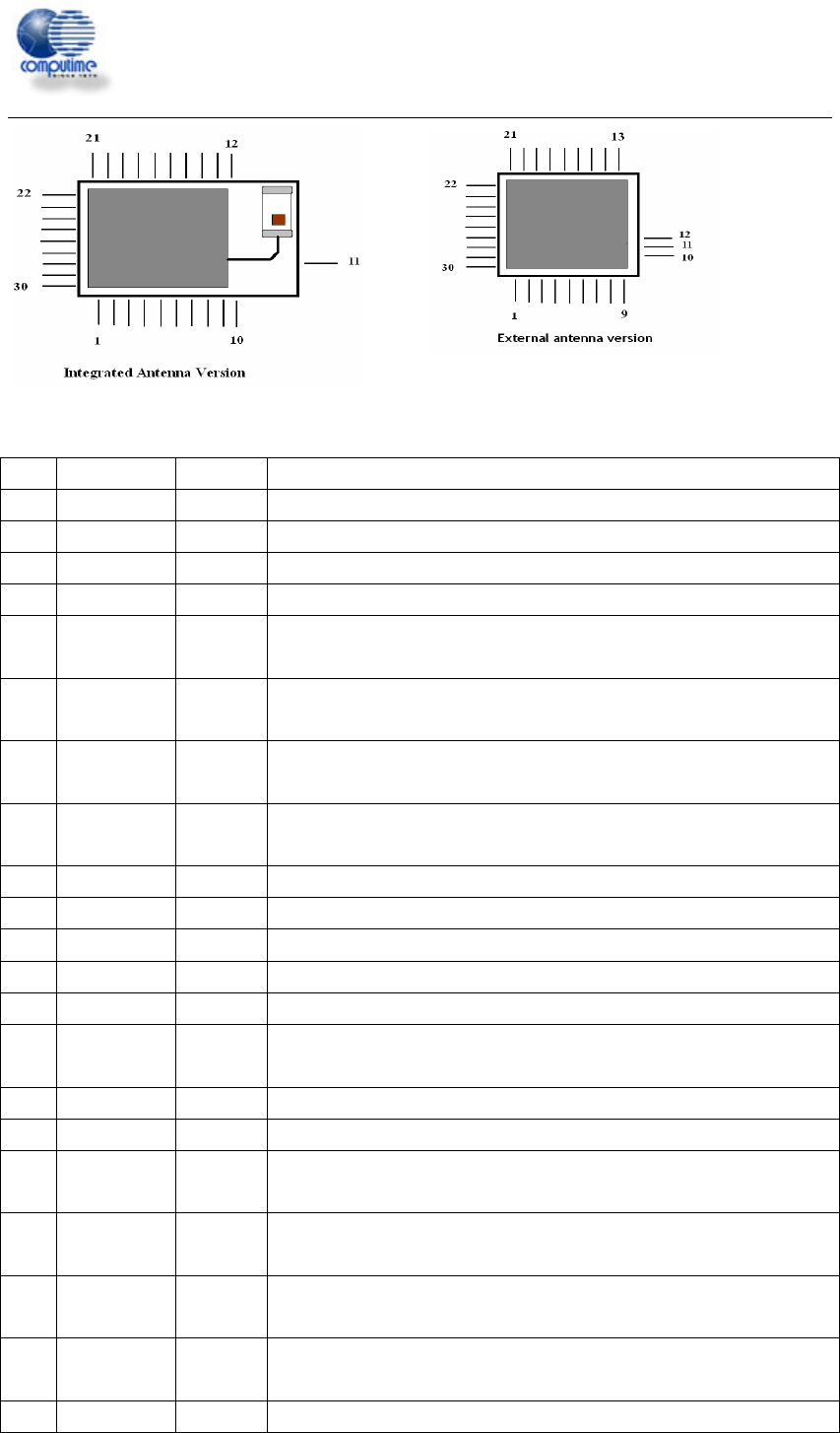
Pin Description
Pin# Signal Direction Description
1 SIF_MISO O Serial interface, master in/slave out
2 SIF_MOSI I Serial interface, master out/slave in
3 SIF_LOADB I/O Serial interface, load strobe (open-collector with internal pull-up)
4 GND Ground Ground supply
5 GPIO16
I/O
Digital I/O
Enable GPIO16 with GPIO_CFG[3]
6 GPIO15
I/O
Digital I/O
Enable GPIO15 with GPIO_CFG[2]
7 GPIO14
I/O
Digital I/O
Enable GPIO14 with GPIO_CFG[1]
8 GPIO13
I/O
Digital I/O
Enable GPIO13 with GPIO_CFG[0]
9 GND Ground Ground supply
10 GND Ground Ground supply
11 ANT I/O receiver input/transmitter output
12 GND Ground Ground supply
13 nRESET I Active low chip reset (internal pull-up)
14 OSCB I/O 24MHz crystal oscillator or left open when using external clock input on
OSCA
15 OSCA I/O 24MHz crystal oscillator or external clock input
16 VBRD Power Pads supply (2.1-3.6V)
17 GPIO11 I/O
Digital I/O
Enable GPIO11 with GPIO_CFG[7:4]
18 GPIO12 I/O
Digital I/O
Enable GPIO12 with GPIO_CFG[7:4]
19 GPIO0
I/O
Digital I/O
Enable GPIO0 with GPIO_CFG[7:4]
20 GPIO1
I/O
Digital I/O
Enable GPIO1 with GPIO_CFG[7:4]
21 GPIO2 I/O Digital I/O