
User's Manual

Quantum™ RFID Pg. 2 of 6
© SAFLOK WL 7/07
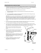
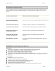
Mortise
Screws
Motor
Wire
Fig. 1
Preparing the door and door frame
1. Prepare the door using the Quantum RFID installation template or drill fixture. The door edge prep is
a standard, full-mortise prep for a 1-1/4” x 8” front plate (1” x 8” and 1” x 7-3/4” custom front plates are
optional). The door surface holes and mortise are customized for the SAFLOK trim.
Important: Some holes are only on the inside surface of the door.
For new construction installations, the door manufacturer may prepare the door using the
installation template.
For retrofit installations, remove the existing hardware and confirm that the existing door edge
prep is appropriate for the SAFLOK mortise lock.
Drill fixture: If you are using a SAFLOK drill fixture, position and clamp the fixture on the door. The
fixture has two positioning posts that rest inside the mortise, establishing the proper backset for the
trim. When the fixture is clamped, its surfaces should be parallel with the door surfaces and door
edges. Not all holes go through the door (refer to the template). Notch the material on the inside
surface for easier routing of the motor wire. After machining, remove any debris from the mortise and
cutouts.
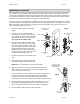
2. Prepare the door frame using the template and install the strike plate using the screws provided
(12 x 1-1/2 screws for wood frames, 12-24 x 3/8 screws for metal frames).
3. The mortise plate has an adjustable bevel. Align the mortise front plate with the bevel of the door
edge and tighten the two bevel adjustment screws at the top and bottom of the mortise case. Position
the mortise case in the door edge with the motor wire routed through the notch (see Fig. 1).
Note: Use care to ensure that the wires do not get
pinched or pulled as the mortise is inserted into the
pocket.
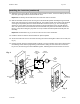
4. Attach the mortise front plate to the door using the two
mortise screws (12 x 1-1/4 screws for wood doors,
12-24 x 3/8 screws for metal doors). Be sure that the
screws are fully tightened.
Important: DO NOT leave the screws loose. The screws
must be fully tightened before the trim is installed. If you
must leave the mortise loose to install the trim, the door
preparation is incorrect.
5. Install the scalp plate with the 8-32 x 1/4 screws
provided and test for proper mechanical latch
engagement into the strike plate.
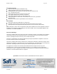
Mortise Front Plate
Notch for routing
the motor wire
(inside only)
Inside Door
Surface