
User Manual

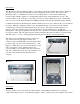
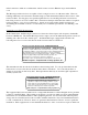
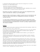

Figure 1
Introduction
The Messenger system is a hybrid solution to networking locks in a hospitality environment. Each door
lock has a low power, limited bandwidth, and short-range digital radio system. The lock uses this
Messenger radio to communicate use history and operating status to a local wireless Messenger
transceiver hub, which is capable of communicating with as many as 64 individual door locks. The
transceiver hubs are all connected to a host PC via a wired or wireless Ethernet network. The host PC
acts as a server for both the Saflok Windows 6000 operating system and the Saflok Messenger database.
Communication between the Messenger database and the locks is two-way; either the host or lock initiates
messages. Messages originating at the lock are transmitted directly to the transceiver hub, which is
continuously powered and predominantly in the receive mode. The transceiver hub then acts as a
gateway device, decoding the wireless message from the lock and transferring it to the Ethernet
infrastructure. Messages originating at the host are sent to the transceiver hub via the Ethernet and stored
in a memory buffer. The lock wakes up periodically and checks the transceiver hub for stored messages,
and then returns to “sleep,” enabling long life from the primary batteries operating the Saflok.
The radio device is installed in the upper plastic end
cap of the inside trim (See Figure 1 and 2.) and
connects to the locks PCB with a four-wire harness that
provides both power and serial communications. (See
Figure 3.) When the lock is produced at the factory, the
radio is plugged in, tested, and then turned off to
conserve battery power during transit and construction.
The radios shall be left in the off position until the door
lock and network infrastructure installations are
complete.
Site Design
Transceiver hub locations are the most critical element of establishing a reliable and cost effective
wireless Messenger network. An insufficient quantity of hubs or incorrectly positioned hubs may result in
Figure 2
Figure 3