
User manual


Computer Gateway User Manual B-3 5/96
B.2.2
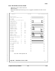
B.2.2 RS-449 Standard (Modem Connection) Cable
• 15 meters, male-to-male connection
• Modem connected
• Both transmit and receive clocks are supplied by the modem
• RS-449 standard connector-pin assignment
Shield ground
Signal ground/common return
not used
not used
Line present (not RS-449 spec.)
Logic ground
Transmitted data (-) TP1
Transmitted data (+) TP1
Transmit clock (+) TP2
Transmit clock (-) TP2
Received data (-) TP3
Received data (+) TP3
Request to send (+) TP4
Request to send (-) TP4
Receive clock (+) TP5
Receive clock (-) TP5
Clear to send (+) TP6
Clear to send (-) TP6
not used
not used
Data set ready (+) TP7
Data set ready (-) TP7
Data terminal ready (+) TP8
Data terminal ready (-) TP8
Rcvd line signl detect (+) TP9
Rcvd line signl detect (-) TP9
not used
not used
not used
not used
not used
not used
Terminal timing (+) (not used)
Terminal timing (-) (not used)
not used
not used
not used
1 1
19 19
2 2
20 20
3 3
21 21
4 4
22 22
5 5
23 23
6 6
24 24
7 7
25 25
8 8
26 26
9 9
27 27
10 10
28 28
11 11
29 29
12 12
30 30
13 13
31 31
14 14
32 32
15 15
33 33
16 16
34 34
17 17
35 35
18 18
36 36
37 37
Function CG Side Modem Side
Note: TPn = Twisted pair line #n
Figure B-2 — RS-449 Standard (Modem) Cable 3221