
User Manual Part 1
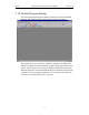
Table Of Contents
- Table of Contents
- 1. Overview
- 2. Quick Installation
- 3. Detailed Installation
- 4. Upgrades
- 5. Software Overview
- 6. Recording Wizard

15
Merlin Protocol Analyzer User’s ManualCATC Version 1.6
G. P. O U T
G.P. OUT needs to be enabled before it will output signalling. See “Blue
Dot Menus for the Event Buttons” on page 84 for details on how to enable
output signalling.
If enabled, G.P. OUT will provide signalling each time a trigger event is
detected by the Analyzer. G.P. OUT’s signalling can be set to three
different formats - "Pulse High" provides a 16.66 ns (ground to +5V) signal,
"Pulse Low" a 16.66 ns (+5 V to ground) signal or "Toggle", a signal with
an initial High (+5V) state that alternates with each trigger event between
continuous High (+5 V) and continuous Low (Ground). "Pulse High" is the
default condition. To change the format, see “Enabling High Pulse, Low
Pulse or Pulse Toggle Signal Outputs” on page 84 for details.
Prototype Rework Area
The Breakout Board contains a prototype rework area for making custom
circuits for rapid development. The area consists of plated-through holes, 20
columns wide by 27 rows long. The top row of holes is connected to GND
and the bottom row is connected to +5V. The remaining holes are not
connected. Use the rework area to insert custom components and wire-wrap
their respective signal, power, and ground pins.
3.6 PC Connection
Use the USB cable provided to connect the host computer to the Merlin
Analyzer.
3.7 Antenna Information
According to the Bluetooth™ specifications, Bluetooth™ Antennas should
be placed at least 10 cm apart. It is recommended that Merlin be placed at
least 1 meter away from the nearest device in the piconet under observation.
3.8 Analyzer PC Requirements
• USB connection to the computer (unless using the PC only as a viewer)
• Microsoft Windows 98, Windows 98SE, Windows ME, Windows 2000,
or Windows NT 4.0 for recording and viewing traffic
Note If installing Merlin software on a Windows NT 4.0 system, you will need a special
diskette that is available from CATC.