
User Manual Part 1
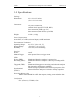
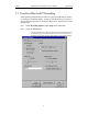
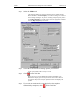
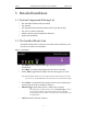
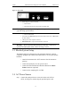
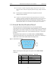
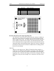
Table Of Contents
- Table of Contents
- 1. Overview
- 2. Quick Installation
- 3. Detailed Installation
- 4. Upgrades
- 5. Software Overview
- 6. Recording Wizard

11
Merlin Protocol Analyzer User’s ManualCATC Version 1.6
3. Detailed Installation
3.1 System Components/Packing List
• One stand-alone Merlin Analyzer module
• One Antenna
• One External Interface Breakout Board with a 9-pin ribbon cable
• One 6-foot (2-meter) USB cable
• Merlin software program installation diskette(s)
• Product documentation
3.2 The Installed Merlin Unit
The Merlin Analyzer has several user-accessible controls and LEDs on its
front and rear panels of the OmniBus.
Figure 1: Front Panel
•Red PWR (power) indicator LED (lights when the unit power is
switched on).
•Green REC (recording) LED (lights when the unit is recording).
• Yellow TRG (triggered) LED (lights when the unit triggers an event).
Note TRG also lights during power-on testing and will be turned off at the end of the
power on cycle. If the LED blinks at the end of this cycle, the hardware is faulty.
•Green SYNC (synchronized) LED (lights when the unit is locked onto a
specific piconet, based on the Master Address).
• Manual Trigger push-button (allows a manual Trace capture)
— After beginning a recording session, press the Manual Trigger switch to
force a Trigger condition. The session completes when a specified
post-Trigger amount of bus data is recorded or when you manually stop a
recording session.
• ANT Bluetooth™ Antenna connector