
User's Manual
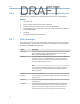
Table Of Contents
- Home
- Contents
- CSI 2140 Machinery Health Analyzer
- Introduction to the analyzer
- Transfer files with CSI 2140
- AMS Machinery Manager Data Transfer
- AMS Machinery Manager Standalone Data Transfer application
- Communication setup
- Routes and jobs
- Load a route from AMS Machinery Manager into the analyzer
- Load multiple routes from AMS Machinery Manager to the analyzer
- Load a Balance job from AMS Machinery Manager into the analyzer
- Dump a job from the analyzer to AMS Machinery Manager
- Dump a route from the analyzer to AMS Machinery Manager
- Dump a route or job from the analyzer to a folder on a computer
- Analyzer firmware and programs
- Screen captures
- Splash screens
- Printing
- Route
- Route overview
- Manage routes
- Set data collection and display parameters
- Set the plot type for collected data
- Enable or disable Point Advance to automatically move to the next measurement point
- Set High Frequency Detection averages
- Set the route data storage mode
- Set the overlap
- Set the plot type for live data
- Set the overall mode
- Set the integrate mode
- Enable or disable multi-channel group data collection
- Display a summary of data collected for grouped measurement points
- View or hide warning alarms on the Route Data Collection screen
- Restore default values for route data collection and display parameters
- Override the sensor setup for a route
- Enter new speed or load for a measurement point
- Tachometers
- Multiple inputs and measurements
- Collect route data
- Notes
- Plot data
- Run Analyze to collect data for a route measurement point
- View the measurement point setup and history
- Route reports
- Plots
- Analyze and Advanced Analyze
- Analyze overview
- Manage jobs
- Job Setup
- View all saved Analyze jobs
- Create an Analyze job
- Open a saved Analyze job
- Change the job ID
- Edit the equipment ID and description in a job
- Edit the measurement ID and description in a job
- Add a measurement
- Delete a measurement
- Delete data from the current measurement point
- Save a job to equipment in a route
- Set display parameters
- Multi-input measurements
- Sensors and inputs
- Tachometers
- Common data collection parameters
- Collecting data using an Analysis Expert
- Recommended uses of Analysis Experts
- Enable or disable the help text in the Analysis Experts
- High Frequency Analysis
- High Resolution Analysis
- Bearing/Gear Analysis - PeakVue
- Low Frequency Analysis - Slow Speed Technology
- Turning Speed Detection
- Laser Speed Detection
- Bump Tests
- Bump Test Equipment Off
- Bump Test Equipment Running
- Coast Down Peak Hold
- Coast Down Peak and Phase
- Rotor Bar Test Motor Current
- Order Tracking
- Synchronous Analysis
- Synchronous Analysis and Synchronous Averaging
- Orbit Plot
- Cross Channel Amplitude/Phase
- Collect data using Manual Analyze
- Listen to live vibration data in Analyze
- Redo a measurement
- Store data to a route or a job
- Review collected data
- Print an Analyze plot to AMS Machinery Manager
- Print a plot to a memory card
- Reset Analyze defaults
- Advanced Transient
- ODS/Modal
- ODS/Modal overview
- Manage jobs
- Sensors and inputs
- Tachometers
- Set up the plots
- Set up the job
- Collect ODS/Modal data
- Display the data for a measurement point
- Print an ODS/Modal plot to AMS Machinery Manager
- Print an ODS/Modal plot to a memory card
- Balance
- Balance overview
- Manage jobs
- Job Setup
- Sensor Setup
- Measurement Plane Setup
- Weight Plane Setup
- Acquire Data
- Balance correction
- Trim run
- One-run balance job
- Notes
- Balance summary reports
- Review balance data
- Manually enter balance job data
- Calculator Mode
- Determine another location to place weights
- Combine multiple weights on a rotor
- Calculate a new balance solution to use only the available weights
- Calculate weight placement using static and couple components
- Estimate trial weights
- Calculate weight location around the outside rotor circumference
- Calculate new balance solution to use only available locations and weights
- Amplification Factor
- Convert magnitude or frequency values to a different measurement unit
- Tips and additional information
- Balance accessories
- Technical specifications
- Glossary
- Index

Option Description
Low Alarm 1 For Dual Lower Delta type alarms, the baseline value minus the Alert value
was exceeded. For Dual Lower Absolute alarms, the Alert value was
exceeded.
Low Alarm 2 For Dual Lower Delta type alarms, the baseline value minus the Alert value
was exceeded. For Dual Lower Absolute alarms, the Fault value was
exceeded.
Low Signal Measured value is less than the weak side setup but greater than the lowest
valid signal level for a Dual Upper Absolute and Out of Window Absolute
type alarm.
Not Measured No measurements were made on this measurement point.
Notes You added a note. Other status messages may override the Notes message.
OK All measurements are within normal amplitude values.
Out Of Service You labeled equipment as out of service. No route data is collected, and the
out of service note is transferred with the route point.
Warning For DU-A type alarms, the baseline value was exceeded but has not reached
the alert level.
Window Alarm The measured values are outside the valid alarm window for an In Window
Absolute Alarm. This is used when a parameter must stay outside a set
range.
Vib Alarm One of the parameters exceeded an alarm level.
4.7 Notes
Notes let you make comments and observations about the equipment you are monitoring.
The analyzer saves notes with your measurement data. When you transfer the route to
AMS Machinery Manager, the note is included with the measurement point.
You can create up to 25 notes on the analyzer. You can also use pre-defined notes created
in AMS Machinery Manager that are included with the route. This lets you quickly add
common notes to a route. Notes are organized by groups, so you can scroll through
groups of similar notes.
4.7.1 Create a note in the analyzer
You can create and modify up to 25 notes in the analyzer. User-defined notes are stored in
internal memory, and they are not removed when you delete routes or route data.
Procedure
1.
Activate a route.
2. From the Route Data Collection screen, press F4 Notes > F2 User Defined Notes > F1
Create User Note.
3. Enter up to 32 characters for the note.
Route
73
DRAFT