
User's Manual
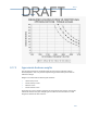

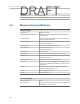
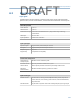

Table Of Contents
- Home
- Contents
- CSI 2140 Machinery Health Analyzer
- Introduction to the analyzer
- Transfer files with CSI 2140
- AMS Machinery Manager Data Transfer
- AMS Machinery Manager Standalone Data Transfer application
- Communication setup
- Routes and jobs
- Load a route from AMS Machinery Manager into the analyzer
- Load multiple routes from AMS Machinery Manager to the analyzer
- Load a Balance job from AMS Machinery Manager into the analyzer
- Dump a job from the analyzer to AMS Machinery Manager
- Dump a route from the analyzer to AMS Machinery Manager
- Dump a route or job from the analyzer to a folder on a computer
- Analyzer firmware and programs
- Screen captures
- Splash screens
- Printing
- Route
- Route overview
- Manage routes
- Set data collection and display parameters
- Set the plot type for collected data
- Enable or disable Point Advance to automatically move to the next measurement point
- Set High Frequency Detection averages
- Set the route data storage mode
- Set the overlap
- Set the plot type for live data
- Set the overall mode
- Set the integrate mode
- Enable or disable multi-channel group data collection
- Display a summary of data collected for grouped measurement points
- View or hide warning alarms on the Route Data Collection screen
- Restore default values for route data collection and display parameters
- Override the sensor setup for a route
- Enter new speed or load for a measurement point
- Tachometers
- Multiple inputs and measurements
- Collect route data
- Notes
- Plot data
- Run Analyze to collect data for a route measurement point
- View the measurement point setup and history
- Route reports
- Plots
- Analyze and Advanced Analyze
- Analyze overview
- Manage jobs
- Job Setup
- View all saved Analyze jobs
- Create an Analyze job
- Open a saved Analyze job
- Change the job ID
- Edit the equipment ID and description in a job
- Edit the measurement ID and description in a job
- Add a measurement
- Delete a measurement
- Delete data from the current measurement point
- Save a job to equipment in a route
- Set display parameters
- Multi-input measurements
- Sensors and inputs
- Tachometers
- Common data collection parameters
- Collecting data using an Analysis Expert
- Recommended uses of Analysis Experts
- Enable or disable the help text in the Analysis Experts
- High Frequency Analysis
- High Resolution Analysis
- Bearing/Gear Analysis - PeakVue
- Low Frequency Analysis - Slow Speed Technology
- Turning Speed Detection
- Laser Speed Detection
- Bump Tests
- Bump Test Equipment Off
- Bump Test Equipment Running
- Coast Down Peak Hold
- Coast Down Peak and Phase
- Rotor Bar Test Motor Current
- Order Tracking
- Synchronous Analysis
- Synchronous Analysis and Synchronous Averaging
- Orbit Plot
- Cross Channel Amplitude/Phase
- Collect data using Manual Analyze
- Listen to live vibration data in Analyze
- Redo a measurement
- Store data to a route or a job
- Review collected data
- Print an Analyze plot to AMS Machinery Manager
- Print a plot to a memory card
- Reset Analyze defaults
- Advanced Transient
- ODS/Modal
- ODS/Modal overview
- Manage jobs
- Sensors and inputs
- Tachometers
- Set up the plots
- Set up the job
- Collect ODS/Modal data
- Display the data for a measurement point
- Print an ODS/Modal plot to AMS Machinery Manager
- Print an ODS/Modal plot to a memory card
- Balance
- Balance overview
- Manage jobs
- Job Setup
- Sensor Setup
- Measurement Plane Setup
- Weight Plane Setup
- Acquire Data
- Balance correction
- Trim run
- One-run balance job
- Notes
- Balance summary reports
- Review balance data
- Manually enter balance job data
- Calculator Mode
- Determine another location to place weights
- Combine multiple weights on a rotor
- Calculate a new balance solution to use only the available weights
- Calculate weight placement using static and couple components
- Estimate trial weights
- Calculate weight location around the outside rotor circumference
- Calculate new balance solution to use only available locations and weights
- Amplification Factor
- Convert magnitude or frequency values to a different measurement unit
- Tips and additional information
- Balance accessories
- Technical specifications
- Glossary
- Index

Glossary
a-weighting A frequency shaping method that can be applied to a spectra based upon the
frequency response of the human ear. The resulting spectra represents the loudness
of the various levels as they would appear to the human ear.
alarm An indication that the parameters of a machine have changed in a significant
manner.
alarm limits Amplitude levels that define an alarm condition on the equipment being monitored.
alert An alarm limit calculated by the software which indicates that equipment is
approaching failure. Designated as a "C" alarm in reports.
aliasing An effect that results in erroneous frequency spectra when the frequency of the
signal being sampled is more than 0.5 times the sampling rate. CSI Machinery
Health Analyzers include anti-aliasing filters that eliminate these errors.
amplification Increasing signal amplitude by a desired amount in order to facilitate further
processing of the signal.
amplification factor Mechanical magnification of the true imbalance effect.
amplitude Indicates the strength (magnitude in RMS, peak, peak-to-peak, average, or D.C.) of a
measured signal.
analysis parameter
set
Includes individual analysis parameters, and also contains instructions that tell the
machinery analyzer how to acquire data.
analysis parameters Divides the frequency spectrum into bands that are individually measured and
analyzed.
ball pass frequency
(inner), BPFI
For rolling element bearings, the ball pass frequency (inner), a defect in the inner
race of a bearing.
ball pass frequency
(outer), BPFO
For rolling element bearings, the ball pass frequency (outer), a defect in the outer
race of a bearing.
ball spin frequency,
BSF
Bearing ball spin frequency for rolling element bearings.
bandwidth The analysis frequency range, from lowest to highest, over which data will be
collected. Bandwidth is specified with a minimum and maximum frequency.
baseline A reference spectrum, usually the first spectra collected on a measurement point.
calibration The procedure by which instruments and transducers are checked and adjusted in
order to obtain accurate readings.
component Equipment is made up of one or more components. A component has its own set of
Measurement Points. Components include motors, gearboxes, fans, and pumps, for
example.
correction weight Weight required to correct imbalanced mass.
cross effect Influence exerted by the imbalance in one plane on the vibration of another plane.
cursor A manually controlled marker that can be moved across a spectrum or waveform
plot display indicating time or frequency and amplitude at the cursor location.
cycles per minute,
CPM
The unit of frequency in cycles per minute. Equal to Hz x 60.
Glossary
263
DRAFT