
User's Manual
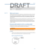
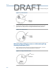
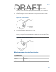
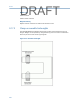
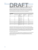
Table Of Contents
- Home
- Contents
- CSI 2140 Machinery Health Analyzer
- Introduction to the analyzer
- Transfer files with CSI 2140
- AMS Machinery Manager Data Transfer
- AMS Machinery Manager Standalone Data Transfer application
- Communication setup
- Routes and jobs
- Load a route from AMS Machinery Manager into the analyzer
- Load multiple routes from AMS Machinery Manager to the analyzer
- Load a Balance job from AMS Machinery Manager into the analyzer
- Dump a job from the analyzer to AMS Machinery Manager
- Dump a route from the analyzer to AMS Machinery Manager
- Dump a route or job from the analyzer to a folder on a computer
- Analyzer firmware and programs
- Screen captures
- Splash screens
- Printing
- Route
- Route overview
- Manage routes
- Set data collection and display parameters
- Set the plot type for collected data
- Enable or disable Point Advance to automatically move to the next measurement point
- Set High Frequency Detection averages
- Set the route data storage mode
- Set the overlap
- Set the plot type for live data
- Set the overall mode
- Set the integrate mode
- Enable or disable multi-channel group data collection
- Display a summary of data collected for grouped measurement points
- View or hide warning alarms on the Route Data Collection screen
- Restore default values for route data collection and display parameters
- Override the sensor setup for a route
- Enter new speed or load for a measurement point
- Tachometers
- Multiple inputs and measurements
- Collect route data
- Notes
- Plot data
- Run Analyze to collect data for a route measurement point
- View the measurement point setup and history
- Route reports
- Plots
- Analyze and Advanced Analyze
- Analyze overview
- Manage jobs
- Job Setup
- View all saved Analyze jobs
- Create an Analyze job
- Open a saved Analyze job
- Change the job ID
- Edit the equipment ID and description in a job
- Edit the measurement ID and description in a job
- Add a measurement
- Delete a measurement
- Delete data from the current measurement point
- Save a job to equipment in a route
- Set display parameters
- Multi-input measurements
- Sensors and inputs
- Tachometers
- Common data collection parameters
- Collecting data using an Analysis Expert
- Recommended uses of Analysis Experts
- Enable or disable the help text in the Analysis Experts
- High Frequency Analysis
- High Resolution Analysis
- Bearing/Gear Analysis - PeakVue
- Low Frequency Analysis - Slow Speed Technology
- Turning Speed Detection
- Laser Speed Detection
- Bump Tests
- Bump Test Equipment Off
- Bump Test Equipment Running
- Coast Down Peak Hold
- Coast Down Peak and Phase
- Rotor Bar Test Motor Current
- Order Tracking
- Synchronous Analysis
- Synchronous Analysis and Synchronous Averaging
- Orbit Plot
- Cross Channel Amplitude/Phase
- Collect data using Manual Analyze
- Listen to live vibration data in Analyze
- Redo a measurement
- Store data to a route or a job
- Review collected data
- Print an Analyze plot to AMS Machinery Manager
- Print a plot to a memory card
- Reset Analyze defaults
- Advanced Transient
- ODS/Modal
- ODS/Modal overview
- Manage jobs
- Sensors and inputs
- Tachometers
- Set up the plots
- Set up the job
- Collect ODS/Modal data
- Display the data for a measurement point
- Print an ODS/Modal plot to AMS Machinery Manager
- Print an ODS/Modal plot to a memory card
- Balance
- Balance overview
- Manage jobs
- Job Setup
- Sensor Setup
- Measurement Plane Setup
- Weight Plane Setup
- Acquire Data
- Balance correction
- Trim run
- One-run balance job
- Notes
- Balance summary reports
- Review balance data
- Manually enter balance job data
- Calculator Mode
- Determine another location to place weights
- Combine multiple weights on a rotor
- Calculate a new balance solution to use only the available weights
- Calculate weight placement using static and couple components
- Estimate trial weights
- Calculate weight location around the outside rotor circumference
- Calculate new balance solution to use only available locations and weights
- Amplification Factor
- Convert magnitude or frequency values to a different measurement unit
- Tips and additional information
- Balance accessories
- Technical specifications
- Glossary
- Index

9.16.4 Identify the correction planes
You can balance a rotor system exactly in N+2 planes (where N = the number of shaft
criticals below operating speed). Most mechanical systems are designed to operate below
their first shaft critical, so use 0 + 2 = 2 planes. Virtually all systems operate below their
fourth critical, so use 3 + 2 = 5 planes. Sometimes a single shaft has only two balance
planes, which normally allows an acceptable balance compromise, even if not exact.
Consider the following:
• The vendor may supply standard positions, such as balance rings.
• For a uniform rotor operating below the first critical, locate a single plane anywhere
for an adequate balance.
• If the rotor operates above the first critical and you use two-plane balancing, locate
the correction planes 25 percent of the distance between bearings.
• For non-uniform rotors, apply the correction weights first to the planes with the
greatest mass moments of inertia.
• Do not add correction weights at any location that affects the rotor stiffness or
modifies the aerodynamics or flow of the system.
9.16.5 Troubleshooting balancing
When field balancing does not give the desired results, it may be due to measurement
errors, weigh placement errors, vibration caused by something other than imbalance, or
lack of understanding of rotor dynamics of system.
If any of the following items occur during the balance procedure, you may not be able to
balance the equipment.
Issue Potential solution
Tachometer readings are
unsteady.
Possible causes:
• Poor speed control of the driving unit.
• Process-related changes, such as fluctuating load.
• A faulty speed reference, such as a poorly aligned photo tach.
• A magnetic pickup placed too far from the shaft.
Because the imbalance force varies with speed, the calculated
influence coefficients may be inaccurate. It is impossible to separate
force changes due to weight placement from those due to speed.
Trial run weights do not
produce at least a 30
percent change in the
imbalance vector for at least
one measurement location.
Use a heavier trial weight or different trial weight location to
increase the percentage change. Changes less than 30 percent can
cause incorrect correction weight calculations.
1xRPM magnitude and
phase do not average to the
same value after repeated
attempts, even with long
averaging times (several
minutes).
Get a synchronous average of the peak or acquire a high resolution
spectra to confirm the peak is 1xRPM. If the readings are not
consistent and repeatable, the calculated balance correction is
invalid.
Loose parts may cause this issue.
Balance
245
DRAFT