
User's Manual
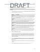
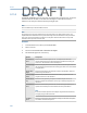
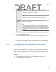
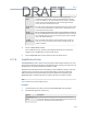
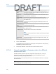
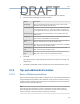
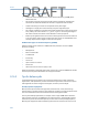

Table Of Contents
- Home
- Contents
- CSI 2140 Machinery Health Analyzer
- Introduction to the analyzer
- Transfer files with CSI 2140
- AMS Machinery Manager Data Transfer
- AMS Machinery Manager Standalone Data Transfer application
- Communication setup
- Routes and jobs
- Load a route from AMS Machinery Manager into the analyzer
- Load multiple routes from AMS Machinery Manager to the analyzer
- Load a Balance job from AMS Machinery Manager into the analyzer
- Dump a job from the analyzer to AMS Machinery Manager
- Dump a route from the analyzer to AMS Machinery Manager
- Dump a route or job from the analyzer to a folder on a computer
- Analyzer firmware and programs
- Screen captures
- Splash screens
- Printing
- Route
- Route overview
- Manage routes
- Set data collection and display parameters
- Set the plot type for collected data
- Enable or disable Point Advance to automatically move to the next measurement point
- Set High Frequency Detection averages
- Set the route data storage mode
- Set the overlap
- Set the plot type for live data
- Set the overall mode
- Set the integrate mode
- Enable or disable multi-channel group data collection
- Display a summary of data collected for grouped measurement points
- View or hide warning alarms on the Route Data Collection screen
- Restore default values for route data collection and display parameters
- Override the sensor setup for a route
- Enter new speed or load for a measurement point
- Tachometers
- Multiple inputs and measurements
- Collect route data
- Notes
- Plot data
- Run Analyze to collect data for a route measurement point
- View the measurement point setup and history
- Route reports
- Plots
- Analyze and Advanced Analyze
- Analyze overview
- Manage jobs
- Job Setup
- View all saved Analyze jobs
- Create an Analyze job
- Open a saved Analyze job
- Change the job ID
- Edit the equipment ID and description in a job
- Edit the measurement ID and description in a job
- Add a measurement
- Delete a measurement
- Delete data from the current measurement point
- Save a job to equipment in a route
- Set display parameters
- Multi-input measurements
- Sensors and inputs
- Tachometers
- Common data collection parameters
- Collecting data using an Analysis Expert
- Recommended uses of Analysis Experts
- Enable or disable the help text in the Analysis Experts
- High Frequency Analysis
- High Resolution Analysis
- Bearing/Gear Analysis - PeakVue
- Low Frequency Analysis - Slow Speed Technology
- Turning Speed Detection
- Laser Speed Detection
- Bump Tests
- Bump Test Equipment Off
- Bump Test Equipment Running
- Coast Down Peak Hold
- Coast Down Peak and Phase
- Rotor Bar Test Motor Current
- Order Tracking
- Synchronous Analysis
- Synchronous Analysis and Synchronous Averaging
- Orbit Plot
- Cross Channel Amplitude/Phase
- Collect data using Manual Analyze
- Listen to live vibration data in Analyze
- Redo a measurement
- Store data to a route or a job
- Review collected data
- Print an Analyze plot to AMS Machinery Manager
- Print a plot to a memory card
- Reset Analyze defaults
- Advanced Transient
- ODS/Modal
- ODS/Modal overview
- Manage jobs
- Sensors and inputs
- Tachometers
- Set up the plots
- Set up the job
- Collect ODS/Modal data
- Display the data for a measurement point
- Print an ODS/Modal plot to AMS Machinery Manager
- Print an ODS/Modal plot to a memory card
- Balance
- Balance overview
- Manage jobs
- Job Setup
- Sensor Setup
- Measurement Plane Setup
- Weight Plane Setup
- Acquire Data
- Balance correction
- Trim run
- One-run balance job
- Notes
- Balance summary reports
- Review balance data
- Manually enter balance job data
- Calculator Mode
- Determine another location to place weights
- Combine multiple weights on a rotor
- Calculate a new balance solution to use only the available weights
- Calculate weight placement using static and couple components
- Estimate trial weights
- Calculate weight location around the outside rotor circumference
- Calculate new balance solution to use only available locations and weights
- Amplification Factor
- Convert magnitude or frequency values to a different measurement unit
- Tips and additional information
- Balance accessories
- Technical specifications
- Glossary
- Index

Procedure
1.
From the Balance main menu, press ALT > F6 Calculator Mode > F11 Units Conv.
2. Enter the values and the units you want to convert.
Option Description
F2 Enter Mag. Enter the magnitude of the vibration units to convert. Enter a value
between 0.00 and 100,000. The default is 0.
F3 Select Mag. Units Enter the vibration units of the magnitude you entered for F2 Enter Mag.
You can display the units in g's, in/sec, mils, mm/sec, or microns. Use
g’s for English units, and use g’s (m) for metric units. The default is mils.
F4 Select Units Type Set the units for the entered frequency. You can use RMS, Peak, and
Peak-to-Peak.
F5 Enter Freq. Enter the frequency of the spectral feature with the magnitude to
convert. Enter a value between 0.01 and 100,000.
F6 Select Freq.
Units
Enter the frequency units of the frequency number you entered for F5
Enter Freq. Select Hertz (Hz) or CPM. The default is CPM.
F9 Select Units Type Specify the units of the calculated solution for acceleration. Select RMS,
Peak, or Peak-to-Peak. The default is RMS.
F10 Select Units
Type
Specify the units of the calculated solution for velocity. Select RMS,
Peak, or Peak-to-Peak. The default is Peak.
F11 Select Units
Type
Specify the units of the calculated solution for displacement. Select
RMS, Peak, or Peak-to-Peak. The default is Peak-to-Peak.
3. Press Enter.
The values for F9, F10, and F11 display the new values in acceleration, velocity, and
displacement.
4.
Press Back or F7 Select Calc. mode to exit and return to the Select Calculation screen.
9.16 Tips and additional information
9.16.1 Basics of balancing machinery
Unless you use the balancing procedure as a diagnostic tool, never attempt field balancing
until you determine the problem is rotor imbalance. Check the rotor resonance, bearing
support resonance, and other system resonances to understand the rotational frequency
in relation to these natural frequencies.
Note
As the operating speed approaches a resonance, amplification and phase shifts can make the
balance job difficult, if not impossible, to perform successfully. As a general rule, the operating
frequency should be 15 to 20 percent above or below these resonances.
Balance
241
DRAFT