
User's Manual
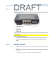
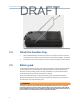
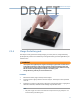
Table Of Contents
- Home
- Contents
- CSI 2140 Machinery Health Analyzer
- Introduction to the analyzer
- Transfer files with CSI 2140
- AMS Machinery Manager Data Transfer
- AMS Machinery Manager Standalone Data Transfer application
- Communication setup
- Routes and jobs
- Load a route from AMS Machinery Manager into the analyzer
- Load multiple routes from AMS Machinery Manager to the analyzer
- Load a Balance job from AMS Machinery Manager into the analyzer
- Dump a job from the analyzer to AMS Machinery Manager
- Dump a route from the analyzer to AMS Machinery Manager
- Dump a route or job from the analyzer to a folder on a computer
- Analyzer firmware and programs
- Screen captures
- Splash screens
- Printing
- Route
- Route overview
- Manage routes
- Set data collection and display parameters
- Set the plot type for collected data
- Enable or disable Point Advance to automatically move to the next measurement point
- Set High Frequency Detection averages
- Set the route data storage mode
- Set the overlap
- Set the plot type for live data
- Set the overall mode
- Set the integrate mode
- Enable or disable multi-channel group data collection
- Display a summary of data collected for grouped measurement points
- View or hide warning alarms on the Route Data Collection screen
- Restore default values for route data collection and display parameters
- Override the sensor setup for a route
- Enter new speed or load for a measurement point
- Tachometers
- Multiple inputs and measurements
- Collect route data
- Notes
- Plot data
- Run Analyze to collect data for a route measurement point
- View the measurement point setup and history
- Route reports
- Plots
- Analyze and Advanced Analyze
- Analyze overview
- Manage jobs
- Job Setup
- View all saved Analyze jobs
- Create an Analyze job
- Open a saved Analyze job
- Change the job ID
- Edit the equipment ID and description in a job
- Edit the measurement ID and description in a job
- Add a measurement
- Delete a measurement
- Delete data from the current measurement point
- Save a job to equipment in a route
- Set display parameters
- Multi-input measurements
- Sensors and inputs
- Tachometers
- Common data collection parameters
- Collecting data using an Analysis Expert
- Recommended uses of Analysis Experts
- Enable or disable the help text in the Analysis Experts
- High Frequency Analysis
- High Resolution Analysis
- Bearing/Gear Analysis - PeakVue
- Low Frequency Analysis - Slow Speed Technology
- Turning Speed Detection
- Laser Speed Detection
- Bump Tests
- Bump Test Equipment Off
- Bump Test Equipment Running
- Coast Down Peak Hold
- Coast Down Peak and Phase
- Rotor Bar Test Motor Current
- Order Tracking
- Synchronous Analysis
- Synchronous Analysis and Synchronous Averaging
- Orbit Plot
- Cross Channel Amplitude/Phase
- Collect data using Manual Analyze
- Listen to live vibration data in Analyze
- Redo a measurement
- Store data to a route or a job
- Review collected data
- Print an Analyze plot to AMS Machinery Manager
- Print a plot to a memory card
- Reset Analyze defaults
- Advanced Transient
- ODS/Modal
- ODS/Modal overview
- Manage jobs
- Sensors and inputs
- Tachometers
- Set up the plots
- Set up the job
- Collect ODS/Modal data
- Display the data for a measurement point
- Print an ODS/Modal plot to AMS Machinery Manager
- Print an ODS/Modal plot to a memory card
- Balance
- Balance overview
- Manage jobs
- Job Setup
- Sensor Setup
- Measurement Plane Setup
- Weight Plane Setup
- Acquire Data
- Balance correction
- Trim run
- One-run balance job
- Notes
- Balance summary reports
- Review balance data
- Manually enter balance job data
- Calculator Mode
- Determine another location to place weights
- Combine multiple weights on a rotor
- Calculate a new balance solution to use only the available weights
- Calculate weight placement using static and couple components
- Estimate trial weights
- Calculate weight location around the outside rotor circumference
- Calculate new balance solution to use only available locations and weights
- Amplification Factor
- Convert magnitude or frequency values to a different measurement unit
- Tips and additional information
- Balance accessories
- Technical specifications
- Glossary
- Index

• Ensure the ambient temperature where the battery pack is located is -4° F to 95° F
( -20° C to 35° C). Due to the chemical composition of Lithium Ion battery
technology, over time there will be some degradation that results in a reduced
charge capacity and performance. This degradation is unavoidable and irreversible.
Prolonged storage at temperatures outside this range, especially temperatures
above the high end, speeds up the degradation process.
• Ensure the battery capacity is approximately 40 percent and periodically recharge
the battery pack (to approximately 40 percent charge capacity) during storage to
ensure the battery does not drain to low levels.
• Disconnect the power supply from the CSI 2140 or the battery pack.
2.5.8 Conserve battery pack power
• Set timers to automatically put the analyzer in standby or turn off the backlight after
a set period of inactivity, such as not pressing any keys or not collecting data. You
can also put the analyzer into standby mode by quickly pressing the power key.
• Set the LCD backlight intensity to "medium". If you use the "High" setting, Emerson
recommends setting the backlight timer to 30 seconds.
These options are available on the General Analyzer Setup screen. Press Home > ALT > F2
General Setup.
2.6 Turn the analyzer on or off
You can set the number of seconds to hold the power key to shut down the analyzer. See
Section 2.9.6.
Procedure
Press and hold the power key
to turn the analyzer on or off.
The Home screen appears when you turn on the analyzer. If you were working in a
program before shutting down, that program appears.
2.6.1 Hard reboot
Do a hard reboot only if the analyzer is unresponsive.
Procedure
Press and hold the power key for approximately 10 seconds until the analyzer shuts
down.
Introduction to the analyzer
13
DRAFT