
User Manual


4-18 Setting Up and Using Laser Alignment Fixtures
Introduction to Laser Alignment Fixtures Setup
This section takes you through a step-by-step setup of the UltraSpec 8215/
8225 Laser Alignment Fixtures. Before performing alignment, be sure all
pre-alignment checks have been completed.
Caution!
Prior to mounting the laser alignment fixtures on machine shafts, all
switches operating the machines should be “locked out.” Follow safety
precautions for your facility. Normally, only personnel performing the
alignment should be able to “unlock” any startup switch. After an
alignment has been completed, the work area should be inspected to
ensure that all equipment is clear of rotating shafts/couplings, prior to
removal of the lockout protection.
Caution!
The 8215/8225 Laser Alignment Fixtures use a Class II (CDRH)
laser or Class 2 (IEC) laser. This laser complies with 21 CFR
1040.10 and 1040.11 safety requirements with a power output < 1.0
mW (average) and a pulse repetition of 600 pulses/sec. The pulse
duration is <110 microseconds. However, do not expose the human eye
directly to the laser beam! Warnings are located on each sensor head.
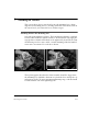
Water vapor or dust can interfere with a target “seeing” its laser. The air
between the sensor heads should be visually clear. Take care to ensure that
the air between the sensor heads is not being heated from steam leaks, unin-
sulated piping, etc. Heated air rising within the span between the sensor
heads can refract the laser beams and cause errors in the alignment read-
ings.
Operate the laser fixtures at ambient temperatures. If the fixtures have been
stored at a different temperature than the ambient temperature, allow the
laser fixtures to reach ambient temperature. Ensure that any heat source
that may be present is not creating a large temperature difference between
the laser fixtures and the ambient temperature. Sunlight itself will not cause
a laser reading problem.