
Manual


Appendix
B-1
B
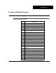
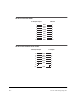
Pinouts and Wiring Diagrams
RS232 D Connector Pinouts
Pin Description
01 Ground (connected to 7, 16, 22)
02 Transmit (RS-232)
03 Receive (RS-232)
04 Connected to 05
05 Connected to 04
06 Connected to 08 and 20
07 Ground (connected to 1, 16, 22)
08 Connected to 06 and 20
09 <Reserved>
10 <Reserved>
11 Transmit (for CSI Modem only)
12 Receive (for CSI Modem only)
13 +5.0 Volts
14 Sensor Button
15 CTS (for CSI Modem)
16 Ground (connected to 1, 7, 22)
17 <Reserved>
18 +9.5 Volts
19 <Reserved>
20 Connected to 06 and 08
21 +10 Volts — Accelerometer Signal Input
22 Ground (connected to 1, 7, 16)
23 Volts In (Signal Input)
24 -10 Volts — Accelerometer
25 <Reserved>