
Manual Chapter 5


5-45
Machine Moves
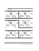
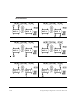
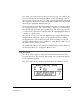
One of the six screens shown on the previous page (top view) will be dis-
played when entering the Horizontal Move section. Just like the Vertical
move section, each screen shows a separate solution to bring the equipment
into alignment. Solutions are expressed in mils or millimeters and show the
direction the equipment should be moved.
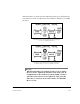
The target indicates how close the machine horizontal or vertical positions
are to being in tolerance. The center (bullseye) indicates an excellent range.
The middle ring represents an acceptable range. The outer ring represents
> 1 times and < 2 times the acceptable range. No ring highlighted indicates
> 2 times acceptable range.
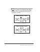
To select the screens, press the Left/Right Arrow to toggle through them.
Except for first reading sets, all the screens default back to the solution
arrangement they were in when last used. For first reading sets, the left
machine will normally be selected. However, when Motor or Move are on
the right side, they will be selected.
To exit Machines Moves and return to the Main menu, press the Enter key.
To enter Live Mode, see “Using Live Mode” below.
Using Live Mode
To activate the live mode in either the Vertical or Horizontal direction,
press the Insert key. The analyzer will prompt you to position the fixtures
to any rotational position.
Place the fixtures at any rotational position and press <Delete> to start.
12