
Manual Chapter 4


4-44 Setting Up and Using Laser Alignment Fixtures
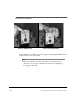
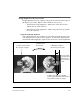
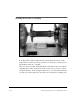
The gridlines on the front panel should assist you in determining the
approximate movement(s) needed to rough the machines in. Gridline
spacing is 0.3 inches (7.5 mm). The following table shows recommended
moves based upon the gross movement of the laser beam on the sensor
head. Gross movements are discussed in vertical terms for simplicity.
Remember, you are seeing the extended centerline of both machines (see
figure below).
3
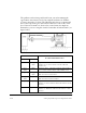
Gross Movement
Recommended Machine Move
at Gearbox at Motor
Small Large,
down
Angular & Offset – add shims under the inboard
Gearbox feet or remove shims from the outboard
Gearbox feet.
Large,
down
Small Angular & Offset – add shims under the inboard Motor
feet or remove shims from the outboard Motor feet.
Large, up Large,
down
Offset – add shims to all feet of the Gearbox or remove
shims from all feet of the Motor.
Large,
down
Large, up Offset – add shims to all feet of the Motor or remove
shims from all feet of the Gearbox.
Large, up Large, up Angular – add shims under the outboard feet of both
machines or remove shims from the inboard feet of both
machines.
Large down Large down Angular – remove shims from the outboard feet of both
machines or add shims under the inboard feet of both
machines.