
Manual Chapter 1


3-14 Options and Hardkey Functions
Address Selection
Address Selection allows the user to read and set the laser head addresses,
to read and set the analyzer address, or to review the laser head and the
analyzer addresses the analyzer is set up to use. This is necessary when
using either direct connect or RF communications. If one laser system (a
system consists of a pair of laser heads and an analyzer) using RF commu-
nication is operating in close proximity to another laser system using RF
communication to prevent the two from interfering with each other. In this
situation either one, more, or all of the laser systems could use direct con-
nect cables to communicate instead of RF communication or the addresses
of each laser system can be changed so that each laser system has a different
address then the other. For example, one laser system can have the address
of its A-head set to 1, B-head to 2, and analyzer to 11 while the other laser
system can have the address of its A-head set to 3, B-head to 4, and analyzer
to 12. A maximum of five (5) laser systems communicating RF can be con-
figured to operate using different addresses. The definition of “operating in
close proximity” will vary from one environment to another. For example,
in one plant any laser system operating within 50 feet of each other could
have RF interference due to the other laser system while in another plant
any laser system operating within 200 feet of each other could have RF
interference due to the other laser system. Refer to “Communication
Between the Fixtures and Analyzer” on page 4-35 for more information.
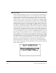
Select Address Selection from under the Options menu and the following
menu will be displayed:
6