Master Guide CM7200 Starter System Firstech, LLC. 21903 68th Ave S. Kent, WA 98032 Phone. 888-820-3690 Fax. 206-957-3330 Please visit techfeed.compustar.
Starter System CM7200 Master Guide techfeed.compustar.
Starter System techfeed.compustar.com Green / White Loop CM7200 Master Guide Copyright 2014 Firstech, LLC.
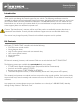
Starter System CM7200 Master Guide techfeed.compustar.com Introduction Thank you for purchasing this Firstech system for your vehicle. The following installation manual is intended for experienced and authorized Firstech technicians. We highly recommend that you contact your local Firstech dealer and seek professional installation. Call 888-820-3690 or visit our website at www. firstechonline.com to locate your nearest dealer.
Starter System CM7200 Master Guide techfeed.compustar.com Installation Basics If you are new to installing Firstech Series Remote Starts and/or Alarms, we highly recommended that you thoroughly review this manual to installing your first unit. Remote Programming: You must code remotes to this system before anything will function.
Starter System CM7200 Master Guide techfeed.compustar.com Remote Programming Routine IMPORTANT: Any and all remotes must be coded to the control module prior to performing any and all operations. STEP 1: Activate programming mode by manually turning the vehicle’s key between the Ign On and Off (or the Acc & On positions) five times within 10 seconds. The vehicle’s parking lights will flash once with the successful completion of this step.
Starter System CM7200 Master Guide techfeed.compustar.com 3. Valet Mode can also be enabled using DroneMobile from the users account at www.dronemobile.com. Once logged in to the user account select the settings tab. Then select the controller settings, check Valet Mode and click Save. (If Valet Mode is already checked, uncheck it and then click save once you have saved it then go back to controller settings, then check valet mode and click save it should enter valet mode).
Starter System CM7200 Master Guide techfeed.compustar.com RPS Touch and car call functions do not require programming, however in order to unlock/disarm your vehicle you must program a 4 digit passcode (numbers 1 through 10 only) you can view our video library for programming instructions at: techfeed.compustar.com Programming Your Code STEP 1: Choose your RPS Touch 4 digit code. ‘0’ is not available. STEP 2: Turn ignition to the ‘ON’ position and leave driver’s door open.
Starter System CM7200 Master Guide techfeed.compustar.com STEP 2: Scroll through the remote options by taping button 3 or 4 (Function button 2W901R-SS). Once the LCD RPS icon flashes reads “RPS-ON” tap button 1 or (Lock button 2W901R-SS) to turn this feature on. The LCD will read “RPS-OFF” STEP 3: Exit remote programming by holding down buttons 2+3 (Trunk and Key/Start 2W901R-SS) buttons simultaneously for 2.5 seconds. The remote will beep indicating that you have successfully exited programming.
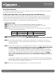
Starter System techfeed.compustar.com CM7200 Master Guide Knock Panel Sensitivity To change knock sensitivity, disarm the system and adjust the switch on the rear of the RPS. The larger the circle, the more sensitive the knock sensor is. FT-DAS (Digital Adjustable Sensor) (Not Programmable with OEM Remotes) The DAS sensor monitors sudden movement forward or backward during the remote start process when starting a manual transmission vehicle.
Starter System CM7200 Master Guide techfeed.compustar.com Testing The DAS Sensor STEP 1: Turn the ignition off and Arm/Lock the system. STEP 2: Wait 30 seconds then test the impact sensitivity. FT-EZGO Setup The FT-EZGO from Firstech will unlock/disarm the vehicle when in range. It is capable of proximity lock/arm and unlock/disarm when in or out of range off the vehicle. There is a manual override button located on the back of the EZ-GO remote.
Starter System CM7200 Master Guide techfeed.compustar.com STEP 2: Proximity locking/unlocking-The main control module will monitor all of the zone inputs that are connected analog or data. In order for the proximity Lock/arm function to work all zones must be closed and ignition off. Once the EZGO remote leaves the proximity of the antenna it will lock/arm within 15 seconds. a.
Starter System CM7200 Master Guide techfeed.compustar.com Jumper 2 (2nd Ignition / 2nd Starter / 2nd Parking light) Jumper 2 sets the behavior of the large blue wire on Connector 1. This wire is powered by an internal relay in the control module. In the default position the jumper is set to 2nd Ignition. 2nd Ignition is common on GM and Toyota vehicles and will need to be powered.
Starter System CM7200 Master Guide techfeed.compustar.com Tach Sensing The default engine sensing mode is tach. In cold weather climates we recommend using an injector wire verses a computer “data” signal, or a coil wire for tachometer sense. IMPORTANT: The remotes must be coded prior to programming tach. Firstech recommends using a digital multimeter when testing for tach. STEP 1: Start the vehicle with the key. Allow time for the engine to idle down.
Starter System CM7200 Master Guide techfeed.compustar.com STEP 1: Change Option 2-10 to setting 3 – Tachless Mode. STEP 2: Process complete – there is no further programming required other than adjusting crank time when necessary (see below). Adjusting Crank Time: To adjust minimum crank times, refer to Option 2-12. To help ensure successful starting, the system will automatically add additional crank time to the 2nd and 3rd start attempts. In addition, there is a built in “Smart Resting Mode”.
Starter System CM7200 Master Guide techfeed.compustar.com 3. The vehicle’s emergency/parking brake wire must be connected to the control module. The proper vehicle wire usually provides a negative (-) trigger while the emergency / parking brake is set. 4. The vehicle’s clutch must be temporarily bypassed ONLY when the remote start cranks the engine. This bypass simulates the clutch being depressed. For complete details on how to wire a momentary clutch bypass visit techfeed.compustar.
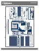
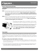
Starter System CM7200 Master Guide techfeed.compustar.com The CM7 Series Blade connector has a locking tab. Non-locking tab blade harnesses will work but you MUST TAKE CARE TO NOT PLUG THE HARNESS IN UPSIDE DOWN. Make sure the two notches on the top of the harness face the top (CM and barcode sticker side) of the brain. When looking at the wire side of the harness the two notches must be at the top of the plug. Blade system includes: 1.
Starter System CM7200 Master Guide techfeed.compustar.com Pin 5 Blue - Programmable Output: Positive 12V (+) output that powers up during remote start. This output is programmable to provide a (+) 2nd ignition (default jumper setting), (+) 2nd Accessory, or (+) parking light output using the jumpers located under the access door on top of the control module. Pin 6 Yellow - Starter 12V positive (+) output. This wire must be connected for remote start.
Starter System CM7200 Master Guide techfeed.compustar.com Pin 1 White: Accessory 12V positive (+) output. This wire must be connected to the vehicle accessory. The proper wire will test 0V with the key in the off position, (+) 12V while key is in the on position, 0V while cranking and back to (+) 12V when the key is returned to the on position. Note: this is a low current accessory output will not support more than 1A (+) Pin 2 Red: Constant 12V positive (+) power input. This wire must be connected.
Starter System CM7200 Master Guide techfeed.compustar.com Pin 2 Brown - Siren: 1A (+) output can be connected to the positive lead of an aftermarket siren. Pin 3 White - [POC 2] Horn:250mA negative (-) output. This is an optional output that will provide a fixed 30mS negative output when triggered by the remote(s). The output control is based on feature 3-08 option setting. Note: There are 28 additional POC setting options for this POC.
Starter System CM7200 Master Guide techfeed.compustar.com Pin 11 Orange - [POC 6] Factory Alarm Arm (FAA) 250mA negative (-) output: This is an optional output that will provide a (-) pulse during lock, after crank and again after the ignition shuts down. The FAA output can be configured using feature 1-05. Note: There are 28 additional POC setting options for this POC.
Starter System CM7200 Master Guide techfeed.compustar.com Pin 18 Yellow/Black - Engine sensing input (A/C): This wire is connected to the vehicle’s Tach or Alternator wire and is required when using the tach and alternator sense setting. (You can also connect this wire to the battery (+) post when using voltage sense to make it more accurate) IMPORTANT: To change engine-sensing modes, you must change Option 2-10; Default option is set for tach input.
Starter System CM7200 Master Guide techfeed.compustar.com Pin 2 Black/White – thermister: temp resistance input. Connector 9 (CN9), 4-Pin to 4-Pin or 6-Pin (Pre-wired Antenna Cable) Connect your antenna cable to this port. You can only use 4 to 4 pin or 4 to 6 pin antenna cables. 6 to 6 Pin antenna cables do not work. Do not use both Connector 9 and Connector 10 at the same time. Pin 1 Yellow - RX input. This wire receives the signal from remote. Pin 2 White - TX output.
Starter System CM7200 Master Guide techfeed.compustar.com Pin 3 Orange/Black - 2nd Unlock 250mA negative (-) output: This is an optional output that will provide a (-) pulse for driver’s priority door lock. IMPORTANT: You must isolate the driver’s door and set feature 1-03 to option 2 (on). Pin 4 Blue - Unlock 250mA negative (-) output: This is an optional output that will provide a (-) pulse for unlocking doors. System will unlock doors and disarm alarm.
Starter System techfeed.compustar.com CM7200 Master Guide Option Programming Tables Option Group 1 Feature Default Setting - I Optional Setting - II Optional Setting - III Optional Setting - IV 1-01 Unlock before, Lock after, starting Off On Lock After Remote Start Only Lock After Shutdown Only 1-02 Lock / Unlock pulse duration 0.8 sec 2.5 sec 0.125 sec 3.
Starter System techfeed.compustar.
Starter System techfeed.compustar.com CM7200 Master Guide Option Group 4 Feature Default Setting - I Optional Setting - II Optional Setting - III Optional Setting - IV 4-01 Aux 1 output 0.5sec Latch 0.5 sec Pulse + Program Program 4-02 Aux 2 output 0.5sec Latch 0.
Starter System techfeed.compustar.
Starter System CM7200 Master Guide techfeed.compustar.com 1-02 Door Lock/Unlock Pulse Duration: This does not affect the behavior of the factory arm output (orange wire) or factory alarm disarm output (orange/white wire). FO1 - 0.8 seconds: (-) Negative lock and unlock output time. FO2 - 2.5 seconds: (-) Negative lock and unlock output time. FO3 - 0.125 seconds: (-) Negative lock and unlock output time.
Starter System CM7200 Master Guide techfeed.compustar.com 1-06 Reservation Lock: Optional manual transmission reservation mode procedures. FO1 - Locks before set: (default) this option will lock the doors before the vehicle engine shuts down to complete reservation mode. This procedure is much safer ensuring that the vehicle cannot be shifted into gear after the engine shuts down and before or during the door locking procedure.
Starter System CM7200 Master Guide techfeed.compustar.com 1-09 Ignition Controlled Locks: When FO 2-4 are selected, the user can activate the “drive lock” or ignition controlled door locking feature using a Firstech remote or Drone. (Please check specific remote user’s manual for steps to activate Drive lock.
Starter System CM7200 Master Guide techfeed.compustar.com 1-13 Double pulse disarm: This feature enables the FAD output. It will pulse 2 times with a single disarm command. FO1 - Off (default): Standard single pulse output on the FAD wire. (orange/white by default) FO2 - On: This feature will generate a double pulse output on the FAD wire. (orange/white by default) 1-14 EZGO: This feature covers the EZGO options.
Starter System CM7200 Master Guide techfeed.compustar.com 2-01 Tach Sensing Method: This feature will determine the point at which the CM7 releases the starter based on the sampled tach method. FO1 - Optimal Tach reading: This option will allow the CM7 to sample the tach signal several times during tach programming and select the optimal tach voltage at which to release the starter. FO2 - Previous tach reading: This option will set the CM7 to record the idle voltage which it is being programmed.
Starter System CM7200 Master Guide techfeed.compustar.com 2-04 Trigger Start: This feature changes the number of pulsed inputs (min of 60mS per pulse) on the trigger start input wire. (Pink wire CN5). Note: If option 3 is selected and OEM remote control feature is available through data, the Control Module will accept 3 OEM lock commands to activate the start sequence.
Starter System CM7200 Master Guide techfeed.compustar.com FO3 - Reserve runtime: (runtime based on feature 2-07 option setting) Note: 2 way LCD remote required. This option will allow the user to set a predetermined time to remote start on the 2 way LCD remote. Once the timer mode is activated it will start the countdown timer on the CM7 based on the difference of time between what the remote clock is set to and the timer mode time is set to. I.e.
Starter System CM7200 Master Guide techfeed.compustar.com 2-10 Engine Sensing: This feature provides 4 options for engine sensing methods. Every CM7 is shipped in manual transmission mode. Tach sensing is our default engine sense option. FO1 - Tach: This option uses a hard wired input (yellow/black CN4 gray connector) to read the vehicles RPM’s in order to release the starter during the remote start process and determine that the engine is running.
Starter System CM7200 Master Guide techfeed.compustar.com 2-14 PIC 1 (-): Programmable Input Channel provides 4 options for negative input to the CM7. FO1 - (-) negative E-brake (aka: parking brake) input: This option allows the CM7 to read input as e-brake which is needed to enter reservation mode or turbo timer mode. (Note: required for manual transmission or turbo timer mode). FO2 - (-) negative parking light reminder input: This option allow the CM7 to read input as parking light reminder.
Starter System CM7200 Master Guide techfeed.compustar.com 3-03 Dome Light Delay: This option is used when connecting the door trigger input to the vehicles dome light circuit. It delays the door trigger input to prevent the door open icon displaying on 2 Way remotes upon lock/arm. FO1- Off: (default) FO2 - 5 seconds: This option will delay the door trigger input for 5 seconds when arming the system to account for any vehicle dome light output delay.
Starter System CM7200 Master Guide techfeed.compustar.com FO4 - On double lock and Start: this option is design to simulate a factory keyless entry system by providing a horn output pulse (based on the option selection of feature 3-02) each time the lock command is sent a second time within 8 seconds of the first. In addition it will provide a horn output pulse with remote start command and remote started confirmation.
Starter System CM7200 Master Guide techfeed.compustar.com 3-12 VAC: (Thermister required) this determines the temperature at which the CM7 will provide an output on any POC programmed with setting 22(VAC: Ventilation-Air Conditioning) which can be used to vent widows, activate AC controls, or cooling seats. FO1 - 100°F: This option will provide a pulsed output on any POC programmed with setting 22 (VAC) if the temp sensor reads at or above 100°F with remote start confirmation.
Starter System CM7200 Master Guide techfeed.compustar.com 3-15 Soft Disarm: this feature will enable Factory Alarm Arm (FAA) and Factory Alarm Disarm (FAD) outputs to trigger when silencing the Compustar siren when sounding with full alarm. FO1 - Off: (Default) this will keep the standard Compustar soft disarm operation.
Starter System CM7200 Master Guide techfeed.compustar.com 4-02 Aux 2 Output: This feature determines the duration of the auxiliary 2 output. (Option 4 allows the output duration to be set for a specific length of time 1-99 sec. and 1-15 min (with OP500 update only) only available when using the OP500) FO1 - 500mS: This option will provide a (-) negative output for 500 milliseconds (0.
Starter System CM7200 Master Guide techfeed.compustar.com FO3 - With Disarm: this option will trigger AUX 2 (output time based on feature 4-02) any time the CM7 is unlocked/disarmed. Note: the system has to be in the armed state when disarming in order to trigger AUX 1. (I.e.
Starter System CM7200 Master Guide techfeed.compustar.com 4-10 PIC 4 (+): (Programmable input Channel 4 CN5 pin 14 Pink) this feature will determine the input function of PIC4. FO1 - Trigger start input: This option will enable PIC4 to be used as a trigger for activating the remote start function using a (+) pulse input on the Pink wire CN5 FO2 - Closed Loop: This option will enable PIC4 to be used as a closed loop input to trigger the CM7 full alarm. This input should see ground when the CM7 is armed.
Starter System CM7200 Master Guide techfeed.compustar.com FO3 - 48hrs (2 days): This option will allow the antenna to power down 48hrs after being armed. Note: once the antenna has powered down, 1 Way operation to the vehicle will stop. 2 Way operation will still function incase any alerts are sent to the remote. In order to wake up the antenna the user must unlock/disarm using a Firstech accessory, power ignition or trigger the alarm.
Starter System CM7200 Master Guide techfeed.compustar.com This special option group allows you to determine the output type of the POC wire. For example, if you want to set POC #5 (default setting status out) to Aux 1, you will need change special option 5 to number 10. This must be done with the OP500.
Starter System CM7200 Master Guide techfeed.compustar.com SV 10 - AUX1: provides a 250mA (-) negative output when AUX is triggered by Firstech 4 button remote, 2way LCD remote, or Drone, on any POC programmed with this setting. SV 11 - AUX2: provides a 250mA (-) negative output when AUX is triggered by Firstech 4 button remote, 2way LCD remote, or Drone, on any POC programmed with this setting.
Starter System CM7200 Master Guide techfeed.compustar.com SV 26 - Unlock: provides a 250mA (-) negative output on any POC programmed with this setting, with the unlock/disarm command. SV 27 - 2nd Unlock: provides a 250mA (-) negative output on any POC programmed with this setting, when using the driver’s door priority feature. This wire would be used to unlock the rest of the doors while unlock should be used to unlock the isolated driver’s door.
Starter System techfeed.compustar.
Starter System techfeed.compustar.
Starter System techfeed.compustar.com CM7200 Master Guide STEP 2: Scroll through menu waiting for 1 parking light flash and/or siren chirp per line. STEP 3: Once finished scrolling through menu, wait for the parking lights and/or siren chirp to confirm the option number. i.e. option 2-04 will flash and/or chirp 4 times. Select your option using the Lock, Unlock, Trunk, or Start buttons. Resetting to Factory Defaults: To reset the options in a particular menu, enter the menu using your remote.
Starter System techfeed.compustar.com CM7200 Master Guide Number of Parking Light Flashes 1 2 3 4 Remote Start Shutdown Error Lost engine sensing signal (Tach/Alternator/Tachless) Lost emergency brake signal (Manual Transmission) Foot brake triggered Hood pin triggered Alarm LED Diagnostics When the alarm is triggered the LED on the RPS (if installed), Secure Valet (if installed) and the LED (if installed) will flash a certain amount of times as shown in the table below.
Starter System CM7200 Master Guide techfeed.compustar.com I need a ground when armed wire, does the control module have one? A: You can use pin 1-blue/white wire on the Grey Connector 5. You must cut this wire and place a diode in line so that when the ignition on the other side of the relay goes to ground and it doesn’t back feed to your accessory. Install the stripe side of the diode facing the control module.
Starter System CM7200 Master Guide techfeed.compustar.com What is this cartridge slot on the CM7000, CM7200, and CM6300? A: This is the slot for the Blade cartridge system. This slot is for the Idatalink Blade remote start bypass modules. For more information on the compatibility and install information please visit compustar.idatalink. com. Using this system eliminates many connections between your standard control module and bypass module.
Starter System CM7200 Master Guide techfeed.compustar.com Technical Support Contacts Firstech technical support is reserved for authorized dealers only. Monday - Friday: 888-820-3690 (8:00 am – 5:00 pm Pacific Standard Time) Email: support@compustar.com Web: techfeed.compustar.com Wiring Diagrams Go to www.firstechonline.com to access Computech3.