
User's Manual


VHF UNIDIRECTIONAL AMPLIFIER TECHNICAL MANUAL
10
Specifications
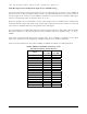
Table IV: General specifications
Description Condition Min Typ. Max Unit
Operating Range and Configuration
Operable Frequency Range
138 - 225 MHz
Nominal Bandwidth
Configurable by the
external channel filters
and di
p
lexers
- - - MHz
Diplexer recommended insertion loss - - 2.0 dB
Channel Filter allowable Insertion Loss - - 4.0 dB
Gain & ALC
Maximum Gain - 100 - - dB
Nominal Gain (at -45dBm input power) no filter nor diplexers - 74 76 dB
Input Manual Attenuation range 2dB step 0 - 30 dB
Automatic Gain Control Range Linear 35 - - dB
Output Level Manual adjustment Range 1dB step 0 - 15 dB
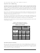
Output Power and Noise (diplexer loss not included)
Limited Output Power Composite power 31 33.5 36 dBm
Output 3
r
d
Order IM Level
2 tones at +26dBm each
- - -14 dBm
Rated Mean Output Power
(diplexer loss not included)
Please see Notice - 32.5 - dBm
Noise Figure Room Temp - 2 4 dB
Port Impedance and Return Loss
Input / Output nominal impedance VGA and PA In/Out - 50 - ohm
Input / Output return loss 50 ohms terminations -12 - - dB
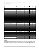
Power Supply
AC power source voltage 50/60Hz 100 - 260 Volt
DC power source voltages
+6Volt/2A and
+48V/1A
+5.4V min to
+12V Max
+48V min to
+52V Max
Mechanical
Dimension in mm (WxDxH) 330 x 175 x 54
Operating Temperature -20 - +55
∘C
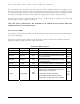
Others
Max Input Power no damage on the VGA
MSA#1 = 0dB att. +14 - - dBm
MSA #1 >= 16dB +30 - - dBm
: Using 12Volt biasing will cause higher temperature on the unit, thus installation having adequate heat evacuation
is required.
NOTICE:
The Manufacturer’s rated output power of this equipment is for single carrier operation. For situation
when multiple carrier signals are present, the rating would have to be reduced by 3.5dB, especially where
the output signal is re-radiated and can cause interference to adjacent band users. This power reduction
is to be by means of input power or gain reduction and not by an attenuator at the output of the device.