
User`s manual


MEASUREMENT PROCEDURE
Settings unique for this application can be made in the Application Set-up.
Which functions that are available depend on which system you have
selected.
The vertical shaft program calculates the shims required under each bolt to
correct angular error and the live display shows the corrections required for
concentricity.
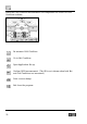
The screen shows the movable machine. The grey areas are data entry
fields. Measure the distance between the TD units. Touch the A field and
enter the value. Confirm with OK. Continue with the B value (Diameter
of bolt pattern) and the number of bolts (max 8). The D measure is by
default set to half the A measure, but can be changed by touching the D
field and entering the correct value. Any values can be corrected if
necessary.
Note: The A dimension is measured from centre to centre of the rods.
55