
User`s manual


OFFSET MEASUREMENT TO ROTATION LINE
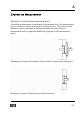
Definition of offset measurements
In applications where the reference is positioned apart from the measurement
object, the zeroing procedure requires a few more steps to ensure the level
of accuracy. (An example here can be a gearbox as a reference measuring
bearing journal positions on a propeller shaft installation.) When determining
the offset of the bearing journals in relation to the reference, it is of
importance that the laser beam describes a prolongination of the reference
centreline.
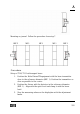
Setup and zeroing
Mount the fixture with T110/T111 close to the rotational centre of the
reference object.
Position the detector as close as possible to the T111. Zero the value on
the display box. (Electrical zeroing).
Rotate the fixture with the T110/T111 180°. Read and halve the value
displayed.
Adjust the laser transmitter until the displayed values are within 0±0,02.
Move the detector to a position on the measurement object as far as
possible away from the T110/T111. Ensure that the laser beam hits
the detector surface.
Eliminate the angular error by rotating the laser transmitter 180° and
257