
User`s manual


ASSEMBLY
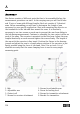
One fixture consists of different parts that has to be assembled before the
measurement procedure can start. In the carrying case you will find 4 hubs
and 12 sets of arms with different lengths. Each set consists of 3 identical
arms. Before assembling you will have to determine the lentgh of arm
necessary for your specific application. Start with mounting the detector or
the transmitter to the hub and then mount the arms. It is absolutely
necessary to use two screws on each arm to prevent the arm from sliding in
the hub during measurement. Continue to assembly the two contact rollers on
each of the arms. The excenter is mounted on the third arm. Adjust the arm
lengths identically on each arm and tighten the screws firmly. The length of
the arm with the excenter is fine tuned. Position the fixture in the bearing
journal and adjust the arm to a length where rotation of the excenter is just
barely possible using the force of one hand. Note! Use no tools. It is of
absolute necessity that the same clamping force is used in every single
measuring point.
1. Hub
3. Adjustable arm
5. Contact roll
7. Screws for receiver attachment
2. Screws for adjustable arm
4. Screw for bracing level
6. Screws for transmitter attachment
8. Bracket for transmitter
250