
Operating instructions

19
Compool Cp3810
Note
To control more than three Valve Actuators, see Valve Module for details.
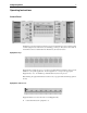
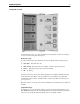
Valve Module
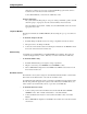
The Valve Module (model MOD-VLV3) allows the system to control three additional Valve
Actuators.
• To install Valve Module
1. Attach Valve Module to the top of the Power Center circuit board.
2. Run Valve Actuator cable(s) to the Valve Module.
3. Plug each Valve Actuator cable into the 3-pin sockets (VLV1, VLV2, or VLV3).
4. Locate the 2-conductor jumper wires included with Valve Module kit. Each individually
controlled Valve Actuator will require a separate jumper wire.
5. Connect one end of the jumper wire into CONTROL JUMPERS socket on the Valve
Module. Connect the other end of the jumper wire into the Power Center circuit board at
the appropriate relay socket (FLTR, AUX1, AUX2, AUX3, AUX4, AUX5, AUX6, EHTR,
SOL PUMP, 2SPD, FLRCL).
6. The D.I.P. switch, located at the upper left-side of Valve Module, allows combining the
operation of Valve Actuators.
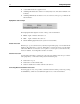
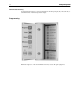
Heat Pump or Electric Heater
These heaters require a relay kit (model RLY-LX) be added. The HTR connection used for gas
heaters cannot used.
• To wire a heat pump or electric heater.
1. At the Power Center, install the relay into the high voltage compartment. Plug control
wire into the EHTR relay socket on the Power Center circuit board.
2. Run a 2-conductor cable the from heater to the Power Center.
3. At the heater, cut thermostat wire and connect to 2-conductor cable.
4. At the Power Center, connect 2-conductor cable to LINE 1 and LOAD 1 of the relay
terminal block.
VLV2
VLV3
VLV1
COMPOOL 11040A
MOD-VLV3
VLV1
WITH
VLV2
12
O
N
AUXILIARY VALVE
ACTUATORS
VLV2
WITH
VLV3
CONTROL JUMPER
SOCKETS