
Operating instructions


18
Compool Cp3810
REM1 Activates AUX1 equipment.
REM2 Activates AUX2 equipment.
REM3 Activates AUX3 equipment
REM4 Activates AUX4 equipment.
REM5 Activates AUX5 equipment.
REM6 Activates AUX6 equipment.
9. Use labels provided to identify each button on the Spa-side Remote.
Note
Install a second Spa-side Remote to control additional functions.
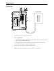
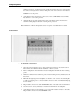
Multiple Control Panels
It is possible to add additional Control Panels.
• To install an additional Control Panel
1. Mount Control Panel as described earlier.
2. Run the communication cable between each Control Panel. Two connectors are provided
on the back of each Control Panel to allow “daisy chaining”.
Note
If two Control Panels are being wired where each communication cable is run back to the
Power Center, a coupler (model 6COND-DUAL) is required.
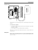
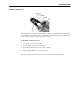
Valve Actuators
Valve Actuators come with 15 feet of cable. If this distance is not long enough, it is possible to
splice in additional wire to lengthen cable. Use 3-conductor wire (model 3COND-CVA).
• To install Valve Actuators
1. Remove knob, handle and four cover screws from the valve to be motorized.
2. Use mounting screws provided to mount Valve Actuator.
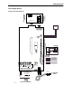
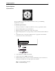
3. Run Valve Actuator cable to the Power Center. Bundle up extra cable under Power Center.
Do not store extra cable in the low voltage compartment.
4. At the top right corner of the Power Center circuit board, plug Valve Actuator cable into
the AUX VLV socket.
5. The AUX VLV socket is most often used to control a solar or cleaner Valve Actuator. To
select which circuit will control the AUX VLV socket, connect jumper wire between
AUX VLV CNTRL socket and relay socket of choice. The system ships with the jumper
connected between AUX VLV CNTRL and SOL PUMP.