Compool Cp3810 AQUATIC CONTROL SYSTEM Installation & Operating Instructions 04/23/97 941-1100
Compool Cp3810 Table of Contents Safety Notice. . . . . . . . . . . . . . . . . . . . . . . . . . . . . . . . . . . . . . . . . . . . . . . . . . . . . . . . . . . . 3 Important Safety Instructions . . . . . . . . . . . . . . . . . . . . . . . . . . . . . . . . . . . . . . . . . 3 Introduction. . . . . . . . . . . . . . . . . . . . . . . . . . . . . . . . . . . . . . . . . . . . . . . . . . . . . . . . . . . . . 4 Package Contents . . . . . . . . . . . . . . . . . . . . . . . . . . . . . . . . . . . . . .
2 Compool Cp3810 Operating Instructions. . . . . . . . . . . . . . . . . . . . . . . . . . . . . . . . . . . . . . . . . . . . . . . . . . . . 25 Control Panel . . . . . . . . . . . . . . . . . . . . . . . . . . . . . . . . . . . . . . . . . . . . . . . . . . . . 25 Equipment Keys . . . . . . . . . . . . . . . . . . . . . . . . . . . . . . . . . . . . . . . . . . . . . . . 25 Equipment Status Icons . . . . . . . . . . . . . . . . . . . . . . . . . . . . . . . . . . . . . . . . .
3 Compool Cp3810 Safety Notice Important Safety Instructions When installing and using this electrical equipment, basic safety precautions should always be followed, including the following: Read and follow all instructions. To reduce the risk of injury, do not permit children to use this product unless they are closely supervised at all times. Water in excess of 100 degrees Fahrenheit may be hazardous to your health.
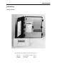
4 Compool Cp3810 Introduction Package Contents The CP3810/S system includes the following components. CP-3810 LX-3810 SNS-KIT2 Control Panel (w/ cable) Power Center Sensor Kit (1 qty.). (1 qty.). (1 qty.).
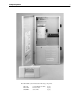
5 Compool Cp3810 The CP3810/SL system includes the following components. CP-3810 LX-3810L SNS-KIT2 Control Panel (w/ cable) Power Center Sensor Kit (1 qty.). (1 qty.). (1 qty.).
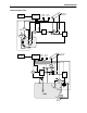
6 Compool Cp3810 Plumbing Requirements FILTER PUMP 11 WATER SENSOR JET PUMP SPA-SIDE REMOTE AIR INTAKE POWER CENTER VACUUM RELIEF SOLAR SENSOR CVA-24 CONTROL PANEL FREEZE SENSOR FILTER 2 HEATER BLOWER 1 SPA SPA LIGHT POWER CENTER FREEZE SENSOR VACUUM RELIEF SOLAR SENSOR SOLAR PUMP HW-5B 6 FILTER 5 CVA-24 FILTER PUMP 4 WATER SENSOR CONTROL PANEL HEATER 3 7 CLEANER PUMP SKIMMER CVA-24 8 POOL LIGHT MAIN DRAIN POOL WATERFALL
7 Compool Cp3810 Plumb system in accordance with recommended hydraulic schematic. 1. If a Spa-side Remote is to be used, install a 3” to 6” length of 1.5” Sch. 40 pvc pipe in the spa wall so that the Spa-side Remote will not be submerged. Positioning the top of the pipe 1/2” below the coping. The pipe should extend beyond the finished surface and will be cut back after tile work is completed. Connect a 1/2” conduit and run back to Power Center. Use sweep elbows for turns. 2.
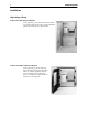
8 Installation High Voltage Wiring Power Center with built in Sub-panel At the equipment pad, mount the Power Center within 15’ of all the equipment. Provide power from the Mainpanel (located at the house) to Power Center. Power Center without built in Sub-panel At the equipment pad, mount a 100 amp electrical circuit breaker panel (Sub-panel) within 15’ of all the equipment. Provide power from Main-panel (located at the house) to the Sub-panel. Mount the Power Center next to the Sub-panel.
9 Compool Cp3810 System Power SUB-PANEL Auto Service ▲ ▲ IMPORTANT: Switch back to Auto after servicing equipment. 3 Hour Filter Override When adding chemicals, the filter pump can be set to stay on for three hours -or- stay off for three hours. This overrides the programming of the Cp3810 indoor controller on a one-time basis. The same procedure can be used on the other equipment keys 1-6.
10 Compool Cp3810 Equipment Power SUB-PANEL LINE 1 LOAD 1 LOAD 2 LINE 1 LINE 2 R2 LOAD 1 LOAD 2 Auto Service ▲ ▲ LINE 1 LINE 2 R3 3 Hour Filter Override When adding chemicals, the filter pump can be set to stay on for three hours -or- stay off for three hours. This overrides the programming of the Cp3810 indoor controller on a one-time basis. The same procedure can be used on the other equipment keys 1-6.
11 Compool Cp3810 Underwater Lights SUB-PANEL LINE 1 LOAD 1 LOAD 2 LINE 1 LINE 2 R2 LOAD 1 LOAD 2 Auto Auto after servicing equipment. Service ▲ LINE 2 R3 3 Hour Filter Override Auto ▲ ▲ P P Auto ▲ ▲ Service LOAD 1 Filter Pump P 1 Instructions: Make sure the Auto/Service key is in the Auto position. 2 Filter Pump On: Press Filter key 2 times quickly. 3 Override Verification: The Auto lamp will blink during the 3-Hour Override.
12 Compool Cp3810 Low Voltage Wiring VLV1 WITH VLV2 1 VLV2 WITH VLV3 2 O N CONTROL JUMPERS COMBINED VALVES VLV1 VLV2 COMPOOL 11040A PART# MOD-VLV3 VLV3 AUXILIARY VALVE ACTUATORS VALVE MODULE (optional) Power Center Circuit Board TRANSFORMER CONNECTIONS 18 24 AUX VLV CNTRL AUX VLV FLTR AUX4 AUX3 AUX5 AUX6 2SPD B/W HEATER ON GAS VALVE CONTROL AUX2 RELAY CONNECTIONS DIMMER 3 AUX1 DIMMER 4 COMPOOL 11099 CAUTION: DO NOT SHORT PINS OF RELAY SOCKETS V PART# PC-LX3810 10 AUX VAL
13 Compool Cp3810 Low Voltage Cables Control Panel 6-conductor cable runs between the Control Panel and the Power Center. Heater Connection 2-conductor cable runs between the heater and the Power Center. Water Temperature Sensor 2-conductor cable runs between the Water Temperature Sensor and the Power Center. Freeze Temperature Sensor 2-conductor runs between the Freeze Temperature Sensor and the Power Center. Caution Do not install low voltage and high voltage wires in the same conduit.
14 Compool Cp3810 Water Temperature Sensor WATER SENSOR GRN RED The Water Temperature Sensor measures pool and spa temperature. • To wire the Water Temperature Sensor 1. Select a convenient location to mount the sensor between the filter pump and filter. 2. Drill a 5/16 inch diameter hole in the pipe and insert the sensor. 3. Position the hose clamp over the sensor, and gently tighten around pipe. Caution Do not overtighten clamp. 4.
15 Compool Cp3810 making connections, cut off stripped ends of cable. Insert the 2 wires to be connected into the connector and squeeze the connector with pliers. Two extra connectors are included. Caution Do not strip wires. 4. At the Power Center circuit board, connect sensor wires to FRZ SENS screw terminals. Pay attention to color-coding of wires. 5. Adjust the Freeze program switch at the bottom of the Power Center circuit board to determine which pumps should turn on during freeze protection.
16 Compool Cp3810 Modular Crimping Tool The Crimping Tool is required to attach modular connectors to the Hookup Cable. The tool may be purchased from a pool supply store (model TOOL-6). If purchasing from an electrical supply store, verify it is designed to crimp 6-position connectors. • To install the modular connectors 1. Use stripper to remove cable jacket. 2. Insert modular connector into crimper slot. 3. Insert cable with blue wire closest to the tool handle. 4.
17 Compool Cp3810 System Options Spa-side Remote The Spa-side Remote is typically installed in the tile-line of the spa. See Plumbing Requirements for details. To install the Spa-side Remote REM6 At the Power Center, connect Spa-side Remote wires to appropriate screw terminals located at bottom of the of the circuit board. REM5 5. REM4 Glue mounting adapter into 1.5” pvc pipe with pvc cement so that the red button will be on top. REM3 4.
18 Compool Cp3810 REM1 REM2 REM3 REM4 REM5 REM6 9. Activates AUX1 equipment. Activates AUX2 equipment. Activates AUX3 equipment Activates AUX4 equipment. Activates AUX5 equipment. Activates AUX6 equipment. Use labels provided to identify each button on the Spa-side Remote. Note Install a second Spa-side Remote to control additional functions. Multiple Control Panels It is possible to add additional Control Panels. • To install an additional Control Panel 1. Mount Control Panel as described earlier.
19 Compool Cp3810 Note To control more than three Valve Actuators, see Valve Module for details. 1 O N 2 VLV2 WITH VLV3 CONTROL JUMPER SOCKETS VLV1 WITH VLV2 COMPOOL 11040A MOD-VLV3 VLV1 VLV2 VLV3 AUXILIARY VALVE ACTUATORS Valve Module The Valve Module (model MOD-VLV3) allows the system to control three additional Valve Actuators. • To install Valve Module 1. Attach Valve Module to the top of the Power Center circuit board. 2. Run Valve Actuator cable(s) to the Valve Module. 3.
20 Compool Cp3810 Solar Heating GRN SOLAR SENSOR RED Solar systems require the following additional equipment, a Solar Temperature Sensor (model TS-5L), a Valve Actuator (model CVA-24T), and a solar valve (model SOL-2T). • To install solar equipment 1. Discard clamp included with sensor kit. For unglazed panels, fasten sensor next to solar panels. For glazed panels, suspend sensor between collector and glazing. 2. Run a 2-conductor cable from the sensor to the Power Center. 3.
21 Compool Cp3810 during these conditions, it is necessary to adjust the HI SPD program switch, which is located at bottom of the Power Center circuit board. Connect RLY-LXD relay control wire into 2SPD relay socket. Manual configuration. The system will run the filter pump in “low speed” during normal filter operation, but will switch the pump to “high speed” when the selected auxiliary circuit is activated.
22 Compool Cp3810 4. Program the backwash interval and duration times at the Control Panel. See Calibration for details. Floor Cleaner Valve The Floor Cleaner Valve is designed to control a dual zone floor cleaning system. The Floor Cleaner Valve can be programmed to rotate once every 1-99 minutes while the filter pump is on. Additional parts required, one Valve Actuator (model CVA-24T) and one 3-port valve (model PTV-2T). • To install the Floor Cleaner Valve 1.
23 Compool Cp3810 Configuration Switches 6 7 8 FREEZE 1 2 3 4 5 6 7 8 I/L SYST 1 2 3 1 2 3 4 HIGH HTR AUX1 SOLR 5 ON DIM3 DIM4 B/W 4 FLRCL 3 CLNR FDEL SOLR HTPMP MANHT 2 FLTR AUX1 AUX2 AUX3 AUX4 AUX5 AUX6 1 ON ON ON SPEC FUNCT HI SPD After setting configuration switches, turn system power off for a few seconds. FREEZE Freeze settings are used to configure the following equipment. FLTR Activate filter pump during freezing conditions.
24 Compool Cp3810 HIGH Activate high speed when spa or pool is on. HTR Activate high speed when heater is on. AUX1 Activate high speed when AUX1 is on. SOLR Activate high speed when solar is on. System Start-up • To perform initial start-up 1. At the Power Center, press the Auto/Service key to select Service mode. 2. Press Equipment keys (Filter, 1, 2, 3, 4, 5, and 6), verify equipment is being activated. 3. Press the Heater key, verify heater fires (Filter pump must also be on).
25 Compool Cp3810 Operating Instructions Control Panel Installed at a convenient location inside the house, the Control Panel provides complete control of all the equipment associated with your swimming pool and spa. The system comes with one Control Panel, however additional Control Panels may be added as needed. Equipment Keys Equipment keys activate the spa or pool, and up to 6 additional items. Each key can be customlabeled for your specific application.
26 Compool Cp3810 A solid OFF indicates the equipment is off. A blinking ON indicates the cleaner is in a safety delay mode. The cleaner will turn on in 5 minutes. A blinking OFF indicates the heater is in a cool down mode. The spa or pool will turn off after 10 minutes. Equipment Status Lamps Three Equipment Status lights are located on the top of the Control Panel. Heater Light on indicates the heater is on. Solar Service Blinking light indicates the system is in Service Mode.
27 Compool Cp3810 Temperature Control Located behind the left door of the Control Panel is the Temperature Control area. Heating choices are selected using the following keys. Heat Source key To select heating method, press the Heat Source key through the different heating options. Solar Only - Heat with solar only. Solar Priority- Heat with solar when available, otherwise switch to gas heater. Heater - Heat with gas heater and solar when available. Off - No heating.
28 Compool Cp3810 Fahrenheit/Celsius key Located behind the right-door of the Control Panel is the Temp. Display key. Press this key to select Fahrenheit or Celsius temperature display. Programming Behind the right door of the Control Panel are the keys used to Program equipment.
29 Compool Cp3810 Programming Typically only the L key (filtration) needs to be programmed. Other Equipment keys can be programmed the same way. • To program filtration 1. Press the Program key. 2. Press the L key. 3. Press the Hours/Minutes key to set the START TIME. 4. Press the Enter key. 5. Press the Hours/Minutes key to set the RUN TIME. 6. Press the Program key to end.
30 Compool Cp3810 Follow Programming example, set START TIME to 0:00 hours. Set RUN TIME to the number of Hour/Minutes before equipment should Time-out. Note If the RUN TIME is set for 24 hours, manually activated equipment will run continuously until manually turned off. Programming a Once-only The Once-only program is used to start the spa after a few hours, for example, you would like to have the spa start in 2 hours. Once the program executes, it is automatically erased.
31 Compool Cp3810 Calibration The temperature sensors, backwash, and floor cleaner valve can be adjusted in the calibration mode. Allow pool to run 5 minutes before calibrating the Water Temperature Sensor. • To calibrate equipment 1. Press the Program key. 2. Press the Spa Heat Source key. 3. Enter correct pool temperature and press Spa Heat Source key. 4. Enter correct solar temperature and press Spa Heat Source key. 5. Enter correct air temperature and press Spa Heat Source key. 6.
32 Compool Cp3810 Note Solar, backwash, and floor cleaner valve adjustments are skipped if feature is not enabled. Tips for calibrating the temperature sensors Water Sensor Let the pool run for 5 minutes to allow water temperature sensor to accurately pickup current pool water temperature. Solar Sensor Put a thermometer into direct sunlight and add 10 degrees to the measurement. Freeze Sensor Shade thermometer from direct sunlight.
33 Compool Cp3810 Power Center Equipment keys Located at the equipment pad, the Power Center provides manual-override capability of your equipment. Caution To prevent water damage, close Power Center door after use. The Auto/Service key toggles the Power Center between the following modes. Auto Service Power Center keys are enabled. Control Panel and Spa-side Remote are disabled. Control Panel and Spa-side Remote are enabled. Power Center keys are disabled.
34 Compool Cp3810 The P key turns on the Filter Pump. Keys 1-6 activate auxiliary equipment. Activates the Heater and Solar. 3 - Hour Filter Override It is possible to override the daily equipment operating cycles, and manually activate (or deactivate) the filter pump and any of the 6 auxiliary circuits for a 3-Hour period. This is particularly useful when adding chemicals to the pool. Note The Control System must be in “Auto” mode to enable these feature.
Compool Cp3810 35 To activate the Heat Boost, press the designated button. The light will blink during the 5-minute cycle to indicate that the spa is being heated. If you wish to turn the heater off at any time during this 5-minute cycle, press the Heat Boost button again. The light will stop blinking to indicate that the spa is no longer being heated.
36 Compool Cp3810 System Options Telephone Module The Telephone Module allows controlling the spa or pool with a phone. To operate from inside the home, pick up the hand set and press 772 or 487, listen for confirming beeps. To operate from outside the home, call the home phone number. The Telephone Module answers the call after 6 rings (if no other device answers the phone first) and confirms with 5 beeps.
37 Compool Cp3810 Problem Solving Display shows “Err 1” If there is a fault with the Water Temperature Sensor, the display will show “Err 1”. Check sensor cable and connections. Replace Water Temperature Sensor (model TS-5L). Display shows “Err 2” If there is a fault with the Solar Temperature Sensor, the display will show “Err 2”. Check sensor cable and connections. Replace Solar Temperature Sensor (model TS-5L).
38 Compool Cp3810 Heat Source does not allow Solar At the Power Center circuit board, the SPEC FNCT configuration switch SOLR needs to be turned on. See Configuration Switches for details. Solar heating stops too soon Verify solar temperature is calibrated correctly. See Calibration for details. Spa-side Remote does not operate At the Control Panel, verify Remote Control at Spa lamp (behind right-side door), is turned on.
Compool Cp 3810 39
40 Index 2-speed Filter Pump Control 36 3 - Hour Filter Override 34 Adding Relays 10 Backwash Control 21 Calibration 31 Canceling Heater and Cleaner Protection 26 Canceling Programs 30 Cleaner Protection 26 Configuration Switches 23 Control Panel 15 Control Panel 25 Dimmer Relay 21 Equipment Keys 25 Equipment keys 33 Equipment Location 7 Equipment Power 10 Equipment Status Icons 25 Equipment Status Lamps 26 Fahrenheit/Celsius key 28 Floor Cleaner Valve 22 FREEZE 23 Freeze Protection 36 Freeze Temperature S
Compool Cp3810 Problem Solving 37 Programming 28 Programming 29 Programming a Once-only 30 Programming a Time-out 29 Programming additional Run Times 29 Remote Control key 30 Safety Notice 3 Sensor Status 34 Setting the Time of Day 30 Solar Booster Pump Control 20 Solar Heating 20 Spa-side Heat Boost 34 Spa-side Remote 17 Spa-side Remote 34 SPEC FUNCT - Special Functions 23 SYST - System 23 System Options 17 System Options 36 System Power 9 System Start-up 24 Telephone Module 21 Telephone Module 36 Tempera