Compool® to EasyTouch® Pool and Spa Control System Upgrade Upgrade MODES OF OPERATION Auto: Indoor control panel and other remote devices operate system. Service buttons on this panel operate system. Other remote devices are disabled. Time Out: Service buttons on this panel operate equipment for three hours, then settings return to Auto mode.
IMPORTANT INFORMATION How to change your Compool/EasyTouch Upgrade system to a “Single Body” system Configuring Compool/EasyTouch as a SINGLE BODY SYSTEM The Compool EasyTouch Upgrade circuit board is factory configured and ready to operate as a SHARED EQUIPMENT system (Jumper J25 = ON). To change the Compool EasyTouch Upgrade board to operate a SINGLE BODY system, first remove Jumper 25 (place the jumper on one of the pins) and erase the EEPROM (see page 49).
i Contents IMPORTANT SAFETY PRECAUTIONS ........................................................................................................ EasyTouch System Kit Contents................................................................................................................... Accessory Equipment ................................................................................................................................... Technical Support ...................................................
ii Contents (Continued) Schedules Menu ........................................................................................................................................... Using the Schedules menu ....................................................................................................................... Schedule your spa/pool pump to turn on ................................................................................................... Using the Once Only feature ..................
iii Contents (Continued) First Time System Start-Up .......................................................................................................................... System Test .................................................................................................................................................. Testing the Auxiliary Relays ..........................................................................................................................
iv IMPORTANT WARNINGS AND SAFETY PRECAUTIONS SERIOUS BODILY INJURY OR DEATH CAN RESULT IF THIS PRODUCTIS NOT INSTALLED AND USED CORRECTLY. INSTALLERS, POOL OPERATORS AND POOL OWNERS MUST READ THESE WARNINGS AND ALL INSTRUCTIONS BEFORE USING THIS PRODUCT. This control system is intended for use in swimming pool applications. Most states and local codes regulate the construction, installation, and operation of public pools and spas, and the construction of residential pools and spas.
v IMPORTANT WARNINGS AND SAFETY PRECAUTIONS For units intended for use in other than single-family dwellings, a clearly labeled emergency switch shall be provided as part of the installation. The switch shall be readily accessible to the occupants and shall be installed at least 10 feet (3.05 m) away, adjacent to, and within sight of, the unit. Except for listed spa-side remote controls, install a minimum of five (5) feet from the inside wall of the pool and spa.
vi Compool to EasyTouch Upgrade System Kit Contents The following items are included in the Compool to EasyTouch Upgrade System kit. • • Compool To EasyTouch Upgrade Kit (P/N 521107) - For upgrading CP3xxx systems Compool To EasyTouch Upgrade Kit with Transformer (P/N 521247) - For upgrading Cp100, Cp1000, Cp2000 system.
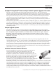
1 Section 1 Overview Compool® EasyTouch® Pool and Spa Control System Upgrade Overview Welcome to the Compool EasyTouch upgrade Pool and Spa Control system − The next generation in automatic control systems. Your Compool EasyTouch upgrade system opens up a wide range of automation features. Your EasyTouch eight auxiliary system allows you to automatically control all of your spa and pool daily operations.
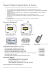
2 Compool EasyTouch Upgrade System Overview Connects to Compool/EasyTouch Upgrade motherboard via RJ12 Adapter or 4-position screw terminal EasyTouch Indoor Control Panel (P/N 520549) (Optional) Low Voltage (DC) circuit breakers EasyTouch Wireless Control Panel (8 circuit) (P/N 520547) (Optional) Upgrade MODES OF OPERATION Auto: Indoor control panel and other remote devices operate system. Service: Service buttons on this panel operate system. Other remote devices are disabled.
3 Compool EasyTouch Upgrade Control Panel Your EasyTouch upgrade system can fully automate your pool, spa functions and any auxiliary circuits (additional pumps and lighting) from the EasyTouch upgrade outdoor control panel or from the optional EasyTouch indoor control panel and EasyTouch wireless control panel. The EasyTouch menu features let you create customized schedules for your pool and spa equipment, heat temperatures, and chlorination settings to switch on and off at a set day and time.
4 Controls and buttons (Continued) ➃ MENU ➄ ➅ Menu/back button: Use this button to access, save and exit from a current menu or sub-menu settings. Also, while in a menu or sub-menu items, use this button to go back to a previous menu level or item. If no menu activity is detected after five minutes, the main screen is displayed. All menu settings are permanently saved and retained in the control panel even after power is removed from the control panel.
5 Controls and buttons (Continued) ➇ Valves (V) - (Pool/Spa/Fill (Spillway)/Drain) button: When in normal operating mode, the Valves (V) button is in “Pool” mode. In this mode the valves are automatically rotated so that only the pool water is circulated through the system and the filter pump is activated. Pressing this button once enables “Spa” mode and activates the filter pump to circulate only spa water through the system.
6 iS4 Spa-Side Remote Controller (Optional) The iS4 Spa-Side remote controller is a doubleinsulated, waterproof device that is UL (1563) listed for installation at the water’s edge. Pentair recommends that the iS4 always be installed above the water line of the spa wall, or in the deck within arm’s reach of a spa occupant. The iS4 provides remote switching of up to four control circuits from the spa location.
7 EasyTouch Indoor and Wireless Control Panel (Optional) The EasyTouch Wireless or the Indoor Control Panel allows you to control your pool and spa daily operations from around your pool area or inside your home. Use the “P” (Pool) and “Spa” (Pool) buttons to heat and filter your pool and spa. The Indoor Control Panel connects to the EasyTouch motherboard in the load center.
8 Compool/EasyTouch Upgrade Outdoor Control Panel Operating Modes The Compool/EasyTouch system can run in automatic mode or manual mode. Use the “Mode” button to switch the system from “Auto” mode (normal operating mode) to “Service” for manual operation and service purposes. Before operating EasyTouch, familiarize yourself with the LCD status messages and operating buttons. Upgrade MODES OF OPERATION Auto: Indoor control panel and other remote devices operate system.
9 Quick Start - Spa and Pool Operations (Shared Equipment) The following describes how to adjust heat temperature for the spa and pool water, schedule a daily run time for the pool/spa filter pump and control lights for shared equipment. Heat your spa or pool AUTO HEATER First enable the heat source (see “Adjust your spa heat settings” below) then press SPA 95°F / 100°F the Valves (V) button to enable “Spa” mode, and press the Filter Pump button to AIR 70°F activate the filter pump.
10 Switch on lights manually and synchronize light colors From the Lights screen you can manually switch all lights on or off, and synchronize colored lights. Up to 12 lights can be controlled. For more information about setting up lights, including IntelliBrite® LED lights and MagicStream® laminars, refer to “Lights Menu” on page 20.
11 Schedule start and stop times for equipment You can set timers (schedules) to automatically run equipment for pool filtration or turn on or off lights. Any EasyTouch circuit can be set to switch on and off on every or any day of the week. Up to 12 total system programs may be created for all circuits combined. Program your Spa or Pool You can use the “Schedule” feature to set the time and day(s) when to switch the filter pump on and rotate the pool/spa valves into the “Pool” or “Spa” position.
12 Setting the Egg Timer Feature The “Egg Timer” feature lets you manually switch on equipment and program the system to automatically switch off after a specified time. You can set this timer feature for other equipment such as lighting, spa, or spa jets. Equipment can be set to be on for one minute or 24 hours. The Egg Timer program is factory set to switch off after 12 hours. You also have the option to use the “Don’t Stop” feature to run a circuit continuously until manually switched off.
13 Section 2 Setting up Compool/EasyTouch Upgrade System Setting up the Compool/EasyTouch Upgrade System for the First Time Use the following steps to setup up the Compool EasyTouch Upgrade system for the first time. 1. Set the system date and time (page 31) Set the current date and time. 2. Assign circuit names (pages 37) Assign the generic default circuit names for output auxiliary equipment. Rename (if necessary) and assign circuit names to the auxiliary (AUX 1, AUX 2) connections.
14 7. Configuring the heater system options (page 25) Set the type of heat source being used (Heater, Solar, Solar Preferred). 8. Configure the iS4, iS10 spa-side remote, QuickTouch wireless remote buttons (page 44) Assign circuits to the iS4, iS10 or QuickTouch remote buttons. Once you have checked that all buttons operate properly, place labels on remote buttons. 9. Set the delays feature (page 43) Enable the one time “delay” feature for the heater, 2-speed pump, and automatic pool cleaner. 10.
15 EasyTouch Menus SETTINGS CLOCK (OPTIONAL) INTELLIFLO INTELLICHLOR 1/2 - ENABLE (YES/NO), POOL MODE: 0 - 100 % (50% default) SPA MODE: 0% (2% default) INTELLICHLOR 2/2 - SUPER CHLR (ON/OFF), RUN HOURS (0 -72) THERMALFLO (OPTIONAL) SETTINGS: ENABLE, DISABLE (NO/YES) - [HEATING, COOLING] - STATUS CIRCUIT NAMES CIRCUIT NAMES (1/18) - [SPA, POOL, AUX 1-7 (ET8), AUX 1-3 (ET4), FEATURE 1-8, AUX EXTRA CIRCUIT FUNC.
16 EasyTouch Menus From the EasyTouch control panel menus you can schedule everyday pool/spa, heating, filtration and cleaning. Lights and laminars can also be scheduled to switch on and off at specific times. The “Settings” and “Schedule” menus are typically used most often for daily spa and pool operations. The “Settings” menu is used by the pool installer to setup installed equipment which is connected to each output relay (filter pump, auxiliary relays, heater, valves, lights, etc.).
17 Feature Circuits Menu There are eight (8) “Feature Circuits” that can be used to control IntelliFlo pump speeds or valves actuators for a spa spillway. Unlike an auxiliary relay circuit, a “Feature” circuit does not connect directly to a relay. “Feature” are turned on and off from the control panel “Feature” circuit menu. Feature Circuits Getting There ▲ Menu F. Circuits To switch a feature circuit ON or OFF: F.
18 Lights Menu From the Lights screen you can manually switch all lights on or off, and synchronize colored lights. Up to eight (8) lights can be independently controlled from the Lights screen. Each light requires a separate auxiliary relay circuit. Up to four lights can be assigned on each auxiliary circuit. A circuit name must be assigned to the AUX relay circuits which controls the light. Verify that IntelliBrite, SAm and/or SAL, and/or FIBERworks have been selected in Circuit Function.
19 Setting up Lights The following section describes how to assign a light circuit name and function to control Pentair Water Pool and Spa IntelliBrite, SAm and/or SAL, and/or FIBERworks lights. Assign the Light Circuit Name and Function The first step in setting up a light circuit is to assign a name to the relay circuit (example; AUX 3, as “Pool Light”), then assign the name “Pool Light” circuit in the Circuit Func. menu as a “light” circuit (IntelliBrite, SAM, SAL..).
20 Setting up lights From the Lights screen you can manually switch all lights on or off, synchronize colored lights, and activate color light shows. Up to eight light circuits can be configured from the “Config” light menu. Each light must have its own relay and separate circuit. Setting up IntelliBrite Light Circuits Before configuring the lights, be sure the auxiliary (AUX) circuits that control the IntelliBrite lights have been assigned as an “IntelliBrite” light.
21 Setting up lights (Continued) Modes (Color Set) The “Color Set” feature allows any combination of up to eight IntelliBrite lights, and Pentair SAm, SAL and or Fiberworks lighting to be preset to specific colors. Fixed light colors are selected and activated from the Colors screen. IntelliBrite Light: If the light was not previously on, after selecting the fixed colored light, no illumination will occur for approximately six (6) seconds followed by the selection.
22 Setting up lights (Continued) Config From the “Config” screen you can setup the IntelliBrite light position, and specify the color of each pool and spa light. Any combination of up to eight IntelliBrite lights, Pentair SAM, SAL and or Fiberworks lights can be preset for specific colors and position when using the “Color Swim” and “Color Set” feature. Fixed light color are selected and activated from the Colors screen. Note: The “Config” menu settings do not apply to the MagicStream laminars.
23 Setting up MagicStream Laminars The MagicStream® Laminar provide a clear, turbulence-free stream of water that is lit with a fiber optic cable, or an LED light for a dazzling nighttime effect. The 12 VAC powered LED light can generate a series of multicolored light shows, or can be set to display a continuous, single color. If desired, the built-in solenoid “thumper” can create a random “wrinkle,” in the Laminar’s stream, causing it to display a brilliant spot of light that moves along the stream’s arc.
24 Using the MagicStream Laminar Features The MagicStream laminar features are displayed in the MagicStream menu. Each time a MagicStream feature is activated, MagicStream resumes with the same features in operation as when last switched off. The MagicStream features are as follows: Toggle Thumper - Pressing this button creates a "wrinkle" in the laminar stream, producing a brilliant spot of light in the laminar arc. Hold - Select Hold to capture the current color effect while colors are changing.
25 Heat Menu Use the heat menu settings to specify the set point temperature and select the heat source for the pool and spa water. The water will begin to heat whenever the heater is manually switched on, (by pressing the Valves (V) button (on the Outdoor Control Panel) or the “Pool” or “Spa” button on the Indoor Control Panel), even if the heater is set to off. The spa will also begin to heat when switched on by the optional iS4/iS10 Spa-Side remote, or EasyTouch wireless remote.
26 Delay Cancel Menu Use the Delay Cancel feature for service or testing purposes. For convenience, on a onetime basis, the Delay Cancel feature will cancel the following safety delays. Please note, generally there is no need to cancel any of the following delays except for servicing or testing the system. • • Heater Cool-Down Delay Cancel: Shuts Filter Pump off immediately. 2-Speed Filter Pump five-minute START on HIGH SPEED Delay Cancel: Shifts pump to low speed.
27 Schedules Menu Use the Schedules menu to create programs to schedule start and stop times to automatically run equipment, such as pumps and lights. Any circuit can be programmed to switch on and off at a specific time on every or any specific day of the week. The number of programs that can be created for circuits are as follows: • • Up to 12 total programs can be created for all circuits combined.
28 Schedules Menu (Continued) Schedule your spa/pool pump to turn on Use the Schedule feature to set the time and day(s) when to switch the filter pump on and rotate the pool or spa valves into the “Spa” or “Pool” position. The heater will automatically heat the spa or pool water up to the set point temperature as set in the “Heat” menu (see page 25). If the pool has a separate jet pump or blower controlled by AUX 1 and/or AUX 2 , these need to be scheduled separately.
29 Using the Once Only feature The “Once Only” feature allows you to program a circuit to switch on at a particular time and day on a onetime basis. A typical use for this feature is to have the spa and heater switch on before you get home from work for one evening. Unlike the regular “Schedule” timer, this feature does not repeat. After this event has finished, the program is automatically erased. The circuit must be switched off manually or wait for the 12 hour automatic shut off.
30 Using the Egg Timer (countdown) Feature The “Egg Timer” feature allows you switch off a circuit automatically after a specified time. The time period is from one minute to 24 hours or run continuously. The “Egg Timer” (countdown) feature is useful for switching off lighting and spa therapy jets.
31 Settings Menu: Clock Use the Clock menu to set the EasyTouch system date and time. The day, time and AM/PM is displayed on the main screen. The system clock settings are used for the EasyTouch system scheduled operations. The EasyTouch system clock will continue to run if power is removed from the EasyTouch system at the load center.
32 Settings Menu: IntelliFlo® (or IntelliPro® pump) The EasyTouch system communicates with the IntelliFlo pump via a two-wire RS-485 cable (PN 350122). For more information about the IntelliFlo pump see the IntelliFlo VS Installation and User’s Guide (P/N 357269), for the IntelliFlo VF pump, see the IntelliFlo VF Installation and User’s Guide (P/N 350075). From the IntelliFlo menu setting the following pumps can be programmed to run at specific U.S.
33 IntelliFlo VF pump To access the IntelliFlo VF menu: Getting There Pump #1 Pump #2 Pump Type Filt.
34 IntelliFlo VF parameters (Continued) Backwash Clean Filt : 10 Flow GPM : 60 Duration : 5 Clean Filter PSI (1 - 50 psi) Default 14 PSI The average PSI setting is between 10 PSI and 20 PSI for most pools and filters. The entered PSI value splits the percentage meter for the filter. When the ""clean filter"" value is reached, EasyTouch displays an alert message and the pump stops monitoring flow rates and starts managing pressure.
35 Settings Menu: IntelliChlor While the EasyTouch system is in normal operating mode (“Pool,” “Spa” mode or “Spa Fill (Spillway),” it will control the IntelliChlor chlorine output level. The amount of chlorine introduced into the pool is determined by the amount of salt in the water, water temperature, and the amount of time the pool pump is running in “Pool” mode. Note: While in “Freeze Protection” mode, IntelliChlor will not operate or produce chlorine during the time that the filter pump is operating.
36 Settings Menu: ThermalFlo® Heat Pump ThermalFlo screen From the ThermalFlo® heat pump screen you can view the current ThermalFlo operation status, and set the unit to operate with for heating only, cooling only, or both heating and cooling if the unit is reversible. Connection from ThermalFlo is via the COM PORT on the EasyTouch motherboard. See page 63 for ThermalFlo to EasyTouch COM port wiring information. The ThermalFlo must be set to default ADDRESS 1.
37 Settings Menu: Circuit Names Labeling Circuit Buttons in the EasyTouch Load Center EasyTouch is factory configured to display each output circuit by its generic name (e.g. AUX 1, AUX 2, etc.). These generic circuit auxiliary names can be assigned a new names which are more descriptive of the equipment being controlled. This makes it much easier to operate all of the pool, spa and lighting equipment without having to memorize what each output controls.
38 EasyTouch Circuit Names AERATOR AIR BLOWER AUX 1 AUX 2 AUX 3 AUX 4 AUX 5 AUX 6 AUX 7 AUX 8 AUX 9 AUX 10 AUX EXTRA BACKWASH BACK LIGHT BBQ LIGHT BEACH LIGHT BOOSTER PUMP BUG LIGHT CABANA LTS CHEM.
39 Settings Menu: Circuit Functions Assigning Circuit Functions From the “Circuit Functions” menu you can assign special logic to the cleaner pump, spa spillway, lights and MagicStream® laminar circuits. For example, when setting up an automatic pool cleaner pump, you would assign the circuit function “MASTER CLEANER.” With this "Cleaner" logic the cleaner pump would force the filter pump on, and the cleaner pump would start after a delay of five minutes.
40 Preset Circuit Functions Generic No special Logic. Simple On/Off control of a circuit with all the programmable capabilities. Master Spa Works with automatic pool cleaner pumps or cleaner valve actuator. It does the following: - Forces the filter pump on 5 minutes before the cleaner pump switches on. - Switch the cleaner off when the spa is on. - Switch the cleaner off for 5 minutes when the solar heating begins. Master Pool Works with automatic pool cleaner pumps or cleaner valve actuator.
41 Settings Menu: Custom Names There are nearly 100 circuit names available to choose from. If you cannot find one to fit your application you can create up to 10 custom names. Each name can be up to 11 alphanumeric characters. After a custom name is saved, it is then available for selection in the Schedules, 2-Speed Pump, iS4 and QuickTouch menus.
42 Settings Menu: 2-Speed Pump Equipment circuits selected in this menu will automatically switch a two-speed filter pump to high speed when these circuits are on. If a two-speed pump is assigned to solar, a cleaner or a pump, when activated the pump will automatically run for five minutes in high speed then switch to low speed. For example, when on, the filter pump will switch to high speed whenever the JETS or CLEANER is on.
43 Solar To enable a solar heater and set the temperature start and run time settings: Solar 1/2 Enable: Yes Heat Pump: No Solar Start: Run : 2/2 6° 4° Up/Down buttons: Select Yes or No to enable solar (1/2). In order to display the solar selection as a heat source in the main screen, select Yes. Right button: Select the Heat Pump setting. Up/Down buttons: Select Yes or No to enable solar as a heat pump.
44 Settings Menu: F° / C° (Fahrenheit/Celsius) The temperature settings for the water, solar and air can be displayed in either Fahrenheit or Celsius. Getting There ▲ MENU ▼ SETTINGS ▼ F˚ / C˚ F˚ / C˚ F° / C° To change the temperature units: F ° / C° FAHRENHEIT Up/Down buttons: Select either Fahrenheit or Celsius. Press the Menu button to save the settings and to return to the Settings menu options.
45 Settings Menu: iS10 Spa-Side Remote Controller You can specify any iS10 Spa-Side remote button to control different functions by assigning each button to a specific circuit. The iS10 has ten assignable circuit buttons; five button on the top row and five buttons on the bottom row. You can also use the “Pump Incrs” and “Pump Decrs” circuit to increase or decrease the pump speed for an IntelliFlo VF (GPM) or VS (RPM) pump.
46 Settings Menu: iSx Pump Cntrl From this menu setting you can specify the IntelliFlo VS or VF pump speed (RPM, GPM) in step increments, for the assigned iS4 or iS10 button using the “Pump Incrs” or “Pump Decrs” circuit (see page 44 and 45). For example, the “Pump Incrs” and “Pump Decrs” circuit can be assigned to any two iS10 buttons. Each press of the assigned “increase” button will increase the pump speed in specific speed increments, as specified in the “iSx Pump Cntrl” menu setting.
47 Settings Menu: QuickTouch (QT4) Wireless Remote The QuickTouch QT4 wireless remote controller provides switching of up to four circuits. For example, you can use the QT4 wireless remote to activate the spa circulation, and for operating three auxiliary pieces of equipment (such as heat enabled, lights, jet pump, heat boost, air blower, waterfall, etc.). Each of the four functions on the QT4 wireless controller has an on and an off button.
48 Settings Menu: Man Heat (Off/On) By default manual heat (Man Heat) is set to “On,” which allows your spa to begin to heat whenever it is manually switched on, (by pressing the Valves (V) button and Filter Pump (F) button on the outdoor control panel or the Spa button on the Indoor Control Panel), even if the Heat menu setting is set to “OFF” (see page 25). Your spa will also begin to heat when switched on by the iS4 Spa-Side remote.
49 Settings Menu: Erase EEPROM (Erase System Memory) EasyTouch system configuration data is stored and retained in “Flash” memory in an EEPROM located on the control panel motherboard and optional Indoor Control Panel. The EasyTouch user system configuration data can be erased to restore the factory defaults settings. System information automatically downloads from programmed components to non-programmed components in case of accidental memory loss and to ease board replacement.
50 Settings Menu: Wireless Addr Use this feature to configure the EasyTouch wireless control panel with a unique communication address to allow the wireless device to operate with the EasyTouch outdoor control panel (see page 62). Wireless Addr Getting There ▲ MENU ▼ SETTINGS ▼ WIRELESS ADDR Press Right arrow button To search and lock on to the EasyTouch wireless control panel: Address Wireless Scanning ...
51 Spa Side [Off/On] Enable or disable the iS4 Spa Side remote. This feature is useful for families with young children or when you go on vacation. It allows you to switch off the iS4 Spa Side remote at the control panel so that the remote cannot be used. Spa Side To enable or disable the iS4 Spa Side remote: Getting There MENU ▼ SPA SIDE [On/Off] Delay Cancel Schedules Settings Spa Side [On ] Right button: Select On or Off to enable or disable the spa side remote.
52 Diagnostics Menu: Self Test Tests the control panel LCD and buttons. Follow the on-screen prompts to perform the tests. Getting There MENU ▼ DIAGNOSTICS ▼ SELF TEST Note: If the Indoor Control Panel is connected to the EasyTouch outdoor control panel, select “LINK CLOSED” in the UART test to abort the UART test. This allows the test to complete with and display PASSED. Firmware Version Press the Right button to display the current software and boot loader revision levels Soft: 1.
53 Diagnostics Menu: Chlorinator Displays the current IntelliChlor chlorination system status. For more information, refer to the IntelliChlor Electronic Chlorine Generator User’s Guide (P/N 520589). Getting There MENU ▼ DIAGNOSTICS ▼ CHLORINATOR Chlorinator Salt Level:3200ppm Status: [OK-NO ERRORS] Menu: Press this button to return to the Settings menu options. Press the button again to return to the main menu options or press again to return to the main screen.
54 Diagnostics Menu: Air Temp Displays the current outside air temperature. Getting There MENU ▼ DIAGNOSTICS ▼ AIR TEMP Air Temperature 72° F Press the Menu button to return to the Settings menu options. Press the button again to return to the main menu options or press again to return to the main screen. Diagnostics Menu: Cir Name: [Off/On] This feature is useful if you have renamed many circuits and want to view the original factory default circuit names.
55 Section 3 Troubleshooting Troubleshooting Use the following troubleshooting information to help resolve problems that may occur when using the EasyTouch system. If by following the recommended actions you are still unable to resolve the problems, please contact Technical Support (see page vi). Frequently Asked Questions (FAQ) How do I setup a two-speed pump? A two-speed pump operates using two relays and one or more circuits. The first relay turns the pump on or off.
56 EasyTouch Error Messages Error Messages If the system detects that a sensor is not connected to the EasyTouch load center or it is defective, an error message is displayed in the “Diagnostics” menu. The following lists the sensor errors. Error Message Possible Cause Solution Air Err (Displays on the Main Screen) Air sensor not connected to the EasyTouch motherboard. Check that the air sensor plug is connected to J21 connector on the motherboard. Check that the sensor wire is connected properly.
57 Maximum Programs Exceeded The “Maximum Programs Exceeded” message displays in the “Schedules” menu if you try to create a new program after exceeding the 12 program limit. To create a new program you must first delete an existing program. For information about deleting a program, refer to “Schedule Menu” on page 27. IntelliChlor Error Messages IntelliChlor status and error messages are displayed in the “Chlorinator” menu (see page 53).
58 System Problem Diagnosis Use the following information to resolve system problems. Problem: The system works in Service Mode, but Indoor Control Panel fails to operate. Symptom Possible Cause Solution Indoor Control Panel has no power - (screen, blank, no LEDs, buttons not working). Bad wiring run from Outdoor Control Panel/motherboard in the Load Center. Verify cable and ensure no connections are broken. In some cases a wire is broken under the insulation.
59 Problem: The Quick Touch remote will not work, or will not work dependably. Symptom Possible Cause Solution POWER LED does not light on the Receiver board located in the plastic clam shell. EasyTouch Load Center does not have power Ensure power is being supplied and that the power center operates correctly without the receiver installed Defective cable or connection to the Load Center Verify the function of the board using known good cable set.
60 Problem: The Quick Touch remote will not work, or will not work dependably (Continued). Symptom Possible Cause Solution Unit seems to turn on or off circuits without the user / transmitter A near by home is operating a similar wireless unit Select an alternate address code for the transmitter and receiver. Change the switches on both receiver and remote to an alternate, but matching setting.
61 First Time System Start-Up The following information describes a basic system start-up procedure. Before you power up the EasyTouch system at the Load Center first check the following: Check Electronics Check that the following plugs are seated correctly on the EasyTouch Load Center motherboard. For connector locations, refer to the EasyTouch System Wiring Diagram on page 60.
62 Setting up the EasyTouch wireless control panel for the first time Setting up the EasyTouch wireless control panel In order for the EasyTouch wireless control panel to communicate with the EasyTouch system outdoor control panel, the first time the wireless device is powered up it must first be assigned a unique communication address. For this process you need to access the menu for each control panel. For convenience it’s easier to setup the wireless device at the outdoor control panel.
63 Synchronizing control panels If the EasyTouch outdoor control panel was previously setup with specific pool and spa information and an additional indoor or wireless control panel with factory default information is installed, during the installation process the outdoor control panel will automatically download the system information to the connected control panel.
64 Blank Page Compool/EasyTouch Pool and Spa Control System Upgrade Installation and User’s Guide
65 Section 4 Compool/EasyTouch Upgrade Kit Installation This section describes how to install the Compool/EasyTouch control panel upgrade kit into a Compool load center or power center. For Compool CP3xxx models complete upgrade list, see page 66 and 67. Compool models TimeMaster, CP/LX100, CP1000, CP2000, CP3000 can also be upgraded to an EasyTouch system.
Compool/EasyTouch Pool and Spa Control System Upgrade Installation and User’s Guide Metal Filter + 7Aux 4 Std/ 8 Max 20 A (2HP) Gas/Elec Solar/Heat Pump 4 @ 230V 1 Std/ 4 Max 0 Std (Required) Compool Type water ( 25ft/air (1ft) Pri: 115/230V Sec:10/18/24 V Enclosure Type Max.
6 Std/ 6 Max 4 Std/ 4 Max 2 Std (Required) 4 Std/ 4 Max 20 A (2HP) Gas/Elec Solar/Heat Pump 4 @ 230V 1 Std/ 4 Max 2 Std (Required) Compool Type water ( 25ft/air (1ft) Pri: 115/230V Sec:10/18/24 V Pwr Relays Relay Amps Compatible Heaters Circuit Brkr Panel & Capacity Valve Actuator Outputs (Aux) Valve Actuators Included w/ System Indoor Control Suppor t Temp Sensors Transformer Type 1 Std/ 4 Max 1 Std/ 4 Max Pri: 115/230V Sec:10/18/24 V Pri: 115/230V Sec:10/18/24 V Pri: 115/230V Sec:
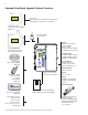
68 Installing Compool/EasyTouch Upgrade Control Panel (with or without Transformer Kit) The following procedure describes how to install the Compool/EasyTouch upgrade control panel (with or without the transformer kit) in a Compool power center (without breaker sub-panel). For Compool/EasyTouch upgrade control panel (with or without the transformer kit) in a Compool load center (with breaker sub-panel), see page 70.
69 Control panel/plate Control panel upper hinge Control panel lower hinge Control panel retaining screw Compool power center (without breaker sub-panel) Control panel upper hinge Upgrade MODES OF OPERATION Auto: Indoor control panel and other remote devices operate system. Service: Service buttons on this panel operate system. Other remote devices are disabled. Time Out: Service buttons on this panel operate equipment for three hours, then settings return to Auto mode.
70 Removal/Replacement of Compool Power Center Transformer Assembly: Switch the main AC power OFF to the Compool power center For Compool CP2000 and older systems remove the existing Compool transformer and replace it with the transformer in the Compool/EasyTouch Upgrade with Transformer Kit (P/N 521247). To remove and replace the Compool power center transformer assembly: 1. Remove the four (4) screws securing the transformer assembly. Save the screws for reinstallation.
71 To install the Compool/EasyTouch Upgrade Transformer Assembly: Switch the main AC power OFF to the Compool power center 1. Mount the new transformer assembly above the low voltage compartment of the power center. Route the three (3) wires through the bushing in the high voltage barrier. See illustration on page 72. 2. Reuse the four mounting screws to secure the transformer assembly. 3.
72 Compool Load Center (with breaker sub-panel) To upgrade the Compool/EasyTouch control panel in a Compool load center (with breaker sub-panel), requires temporary removal of the existing transformer to allow the removal of the Compool control panel from the load center and the installation of the Compool/EasyTouch control panel. To upgrade the Compool/EasyTouch control panel in a Compool load center (with breaker sub-panel), requires removal and reinstallation of the existing transformer.
73 Remove (3) screws Compool TimeMaster/ CP100 power center with time clock (TimeMaster) Removal of Compool transformer assembly: 5. For Compool CP2000 and older systems remove the existing Compool transformer and replace it with the Compool/EasyTouch Upgrade Transformer (P/N 521247). a) Remove the three (3) screws securing the service panel to expose the high voltage compartment in the right side of the load center.
74 Installing the Compool/EasyTouch Upgrade Control Panel (Compool Load Center with sub-panel) Switch the main AC power OFF to the Compool power center To install the Compool/EasyTouch control panel: 1. Hold the transformer assembly to allow the control panel to be mounted, then slide the control panel onto the load center hinges. 2. Mount the transformer assembly in position. Reuse the four mounting screws to secure the transformer assembly. 3.
75 Switch the main AC power OFF to the Compool load center To install the Compool/EasyTouch Upgrade Transformer Assembly: 1. Mount the new transformer assembly above the low voltage compartment of the load center. Route the three (3) wires through the bushing in the high voltage barrier. See illustration on page 72. 2. Reuse the four mounting screws to secure the transformer assembly. 3.
76 UPGRADE WIRING DIAGRAM TRANSFORMER FACTORY WIRING OUTPUT: 10VAC 18VAC 24VAC LOW VOLTAGE CIRCUIT BREAKERS BLU/WH BLU ORG/WH ORG RED/WH RED 10V 18V 24V TRANSFORMER CONNECTIONS 10VAC 18VAC 24VAC IMPORTANT NOTE: CAUTION: DO NOT BYPASS INTERNAL HEATER THERMOSTAT, HIGH LIMIT SWITCH, OR OTHER SAFETY DEVICES.
77 1 VLV2 WITH VLV3 2 O N CONTROL JUMPERS COMBINED VALVES VLV1 VLV2 COMPOOL 11040A PART# MOD-VLV3 VLV3 AUXILIARY VALVE ACTUATORS V A LV E MODU LE (optional) VLV1 WITH VLV2 TRANSFORMER CONNECTIONS PART# PC-LX3810 10 18 AUX VALVE ACTUATOR 24 Low Voltage Wiring AUX VLV CNTRL AUX VLV FLTR AUX4 AUX3 AUX5 AUX6 2SPD B/W H E AT E R ON GAS VALVE CONTROL AUX2 RELAY CONNECTIONS DIMMER 3 AUX1 DIMMER 4 COMPOOL 11099 CAUTION: DO NOT SHORT PINS OF RELAY SOCKETS V Power Center Circuit Bo
78 NOTES Compool/EasyTouch Pool and Spa Control System Upgrade Installation and User’s Guide
NOTES
*521102* P/N 521102 Rev A