&7 — Instructions — CONNECTING EXTERNAL CONTROLLERS to AQUACAL HEAT PUMPS 2737 24th Street North St. Petersburg, FL 33713 727-823-5642 www.aquacal.
Table of Contents Page Introduction to Connecting Controllers to AquaCal Heat Pumps ......3 Personal Safety and Equipment Precautions .................................4 External Controller Overview ..................................................4 Interface Method #1, 2-Wire Controllers ...........................................4 AquaLink 2, 4, 8, and all Aqualink “RS” Series Controllers ..........4 Compool CP3400, CP3600 and CP3800 Controllers ...................
INTRODUCTION... Connecting Controllers to AquaCal Heat Pumps To support direct connection of external controllers, the majority of AquaCal heaters are equipped with a controller options terminal block. External controller connection instructions, for heaters with options terminal blocks, follow within this booklet. A smaller group of AquaCal heaters—while not equipped with an options terminal block—can, through alternate means, be connected to external controllers.
Personal Safety and Equipment Precautions WARNING! Failure to heed the following may result in permanent injury or death. Installation by unqualified persons may result in hazards to installer and others. These instructions are intended for use by qualified installation technicians, familiar with electrical service industry safety standards and methods. Installation to be performed by qualified individuals only. Follow all applicable codes and standards.
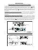
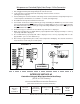
Microprocessor-Controlled (Digital) Heat Pumps: 2-Wire Connection (See Figure-2A) 1. Run (18-gage minimum) low-voltage wiring from controller to heater. 2. Locate microprocessor PC board inside heat pump electrical controls enclosure (See Figure-1A on Page-3). 3. Connect wiring from external controller’s low-voltage heater control terminals to heat pump microprocessor board options terminal block; use terminals: “Y” and “Z” (See Figure-2A). 4. Reestablish electrical power and water flow to heater. 5.
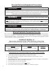
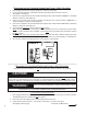
Electromechanically-Controlled (Analog) Heat Pumps: 3-Wire Connection 1. Run (18-gage minimum) low-voltage wiring from controller to heat pump. 2. Locate “Controller Options” terminal block inside heat pump electrical controls enclosure (See Figure-1 on Page-3). 3. Connect one conductor from external controller low-voltage heater control terminal: “COM/OFF,” to “Controller Options” terminal “C” (See Figure-3). 4.
Microprocessor-Controlled (Digital) Heat Pumps: 3-Wire Connection (continued): 1. 2. 3. 4. 5. 6. 7. 8. 9. 1. 2. 3. Programming Heat Pump Microprocessor Make sure pool water pump is on. Restore electrical power to heat pump. Press and hold “UP” and “DOWN” keys, simultaneously, until “CF1” displays. At “Pool/Spa” key, toggle until “LOC” appears. Press “UP” key; go to “50.” At “Pool/Spa” key, toggle until “FS2” appears. Press “UP” key twice. The number “1” should display. WAIT...
2737 24th St. North St. Petersburg, FL 33713 1-727-823-5642 PROBLEMS ? CALL US....