Compool Cp3800 POOL-SPA CONTROL SYSTEM Installation & Operating Instructions 11/07/97 941-1064
Compool Cp3800 Table of Contents Safety Notice. . . . . . . . . . . . . . . . . . . . . . . . . . . . . . . . . . . . . . . . . . . . . . . . . . . . . . . . . . . . 3 Important Safety Instructions . . . . . . . . . . . . . . . . . . . . . . . . . . . . . . . . . . . . . . . . . 3 Introduction. . . . . . . . . . . . . . . . . . . . . . . . . . . . . . . . . . . . . . . . . . . . . . . . . . . . . . . . . . . . . 4 Package Contents . . . . . . . . . . . . . . . . . . . . . . . . . . . . . . . . . . . . . .
2 Compool Cp3800 System Start-up. . . . . . . . . . . . . . . . . . . . . . . . . . . . . . . . . . . . . . . . . . . . . . . . . . . 24 Operating Instructions. . . . . . . . . . . . . . . . . . . . . . . . . . . . . . . . . . . . . . . . . . . . . . . . . . . . 25 Control Panel . . . . . . . . . . . . . . . . . . . . . . . . . . . . . . . . . . . . . . . . . . . . . . . . . . . . 25 Equipment Keys . . . . . . . . . . . . . . . . . . . . . . . . . . . . . . . . . . . . . . . . . . . . . . .
3 Compool Cp3800 Safety Notice Important Safety Instructions When installing and using this electrical equipment, basic safety precautions should always be followed, including the following: Read and follow all instructions. To reduce the risk of injury, do not permit children to use this product unless they are closely supervised at all times. Water in excess of 100 degrees Fahrenheit may be hazardous to your health.
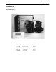
4 Compool Cp3800 Introduction Package Contents The CP3800/T system includes the following components. CP-3800 LX-3800 CVA-24T PTV-2T SNS-KIT2 Control Panel (w/ cable) (1 qty.). Power Center (1 qty.). Valve Actuator (2 qty.). 3-Port Valve (2 qty.). Sensor Kit (1 qty.).
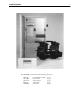
5 Compool Cp3800 The CP3800/TL system includes the following components. CP-3800 LX-3800L CVA-24T PTV-2T SNS-KIT2 Control Panel (w/ cable) (1 qty.). Power Center (1 qty.). Valve Actuator (2 qty.). 3-Port Valve (2 qty.). Sensor Kit (1 qty.).
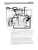
6 Compool Cp3800 Plumbing Requirements CONTROL PANEL FREEZE SENSOR POWER CENTER VACUUM RELIEF SOLAR SENSOR SOLAR PUMP FILTER 9 4 HEATER 6 JET PUMP 7 CVA-24 SPA-SIDE REMOTE AIR INTAKE CVA-24 10 HW-5B WATER SENSOR FILTER PUMP 11 2 SKIMMER 8 5 1 SPA LIGHT 3 CVA-24 BLOWER SPA CVA-24 CLEANER PUMP POOL LIGHT MAIN DRAIN POOL WATERFALL Plumb system in accordance with recommended hydraulic schematic. 1. Spa should be at or above the level of the pool.
7 Compool Cp3800 6. Systems with separate main drain and skimmer lines can use a 3-port valve to balance the flow. 7. Plumb cleaner pump after the return valve to the pool return line. 8. A Valve Actuator can be used to direct pool return water to a waterfall. This eliminates the need for an additional pump. 9. Plumb solar feed and return lines between the filter and heater. Install 3-port solar valve at the feed line. Use Compool solar valve (model SOL-2T), to allow automatic draining of panels.
8 Installation High Voltage Wiring Power Center with built in Sub-panel At the equipment pad, mount the Power Center within 15’ of all the equipment. Provide power from the Main-panel (located at the house) to Power Center. Power Center without built in Sub-panel At the equipment pad, mount a 100 amp electrical circuit breaker panel (Sub-panel) within 15’ of all the equipment. Provide power from Main-panel (located at the house) to the Sub-panel. Mount the Power Center next to the Sub-panel.
9 Compool Cp3800 System Power SUB-PANEL ▲ ▲ ▲ ▲ ▲ ▲ Lx3800 System Power provides power to the transformer. • To wire System Power 1. At the Sub-panel, install a circuit breaker for System Power. The system draws less than 1 amp. Do not use a GFCI circuit breaker. 2. Run appropriate wires from the circuit breaker to the System Power terminal block. 3. For a 115 volt connection, connect to terminals 2 and 3. 4. For a 230 volt connection, connect to terminals 1 and 3.
10 Compool Cp3800 Equipment Power SUB-PANEL LINE 1 LOAD 1 LOAD 2 LINE 1 LINE 2 R2 LOAD 1 LOAD 2 LINE 1 ▲ ▲ LINE 2 R3 LOAD 1 FULL LOAD: 20AMP LOCKED ROTOR: 60AMP LINE 2 R1 LOAD 2 LINE 1 LINE 2 R4 ▲ ▲ LINE 1 LINE 2 R5 ▲ ▲ LOAD 1 LOAD 2 LINE 1 LINE 2 R6 LOAD 1 LOAD 2 LINE 1 HIGH VOLTAGE RELAYS LOAD 1 LOAD 2 LINE 2 R7 LOAD 1 LOAD 2 Lx3800 The diagram above shows how the filter pump is wired. Additional pumps should be wired the same way. • To wire high voltage equipment 1.
11 Compool Cp3800 Underwater Lights SUB-PANEL LINE 1 LOAD 1 LOAD 2 LINE 1 LINE 2 R2 LOAD 1 LOAD 2 LINE 1 ▲ ▲ LINE 2 R3 LOAD 1 FULL LOAD: 20AMP LOCKED ROTOR: 60AMP LINE 2 R1 LOAD 2 LINE 1 LINE 2 R4 ▲ ▲ LINE 1 LINE 2 R5 ▲ ▲ LOAD 1 LOAD 2 LINE 1 LINE 2 R6 LOAD 1 LOAD 2 LINE 1 HIGH VOLTAGE RELAYS LOAD 1 LOAD 2 LINE 2 R7 LOAD 1 LOAD 2 GFCI Lx3800 TO LIGHT High voltage pool/spa lights require GFCI protection.
12 Compool Cp3800 Low Voltage Wiring VLV1 WITH VLV2 VLV2 WITH VLV3 O N CONTROL JUMPERS COMBINED VALVES VLV1 VLV2 COMPOOL 11040A PART# MOD-VLV3 VLV3 AUXILIARY VALVE ACTUATORS VALVE MODULE (optional) Power Center Circuit Board TRANSRER CNNECTINS PART# PC-LX3800 10 18 INTAKE VALVE ACTUATOR 24 RETURN VALVE ACTUATOR AUX VALVE ACTUATOR INT VLV V RET VLV AUX VLV SPA FLTR AUX4 AUX3 AUX5 AUX6 2SPD AUX7 HEATER N AS VALVE CNTRL AUX2 RELAY CONNECTIONS DIMMER 3 AUX1 DIMMER 4 FLRCL PRE
13 Compool Cp3800 Low Voltage Cables Control Panel 6-conductor cable runs between the Control Panel and the Power Center. Heater Connection 2-conductor cable runs between the heater and the Power Center. Water Temperature Sensor 2-conductor cable runs between the Water Temperature Sensor and the Power Center. Freeze Temperature Sensor 2-conductor runs between the Freeze Temperature Sensor and the Power Center. Valve Actuators 3-conductor cable runs between Valve Actuator and the Power Center.
14 Compool Cp3800 AUX VLV CNTRL socket and relay socket of choice. The system ships with the jumper connected between AUX VLV CNTRL and SOL PUMP. Note To control more than three Valve Actuators, see Valve Module for details. Gas Heater Connections HEATER GAS VALVE CONTROL ON OFF PRESSURE LIMIT THERMOSTAT The diagram above shows how to wire a gas heater. • To wire the gas heater 1. Run a 2-conductor cable from the heater to the Power Center. 2.
15 Compool Cp3800 5. At the sensor, use crimp connectors (included) to provide waterproof connections. Before making connections, cut off stripped ends of cable. Insert the 2 wires to be connected into the connector and squeeze the connector with a pair of pliers. Two extra connectors are included. Caution Do not strip wires. 6. At the Power Center circuit board, connect sensor wires to WAT SENS screw terminals. Pay attention to color-coding of wires.
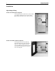
16 Compool Cp3800 Control Panel • To install the Control Panel 1. Select a location inside the house or other weather-protected area to mount the Control Panel. The Control Panel should be installed at or below eye level. 2. Remove backplate from Control Panel. Position backplate and mark the three mounting points. 3. Drill 3/16” diameter holes at the three points. Insert mounting anchors (included) into the three holes. 4. Pull cable through large hole in backplate, use the three 1.
17 Compool Cp3800 Modular Crimping Tool The Crimping Tool is required to attach modular connectors to the Hookup Cable. The tool may be purchased from a pool supply store (model TOOL-6). If purchasing from an electrical supply store, verify it is designed to crimp 6-position connectors. • To install the modular connectors 1. Use stripper to remove cable jacket. 2. Insert modular connector into crimper slot. 3. Insert cable with blue wire closest to the tool handle. 4.
18 Compool Cp3800 System Options Spa-side Remote The Spa-side Remote is typically installed in the tile-line of the spa. See Plumbing Requirements for details. To install the Spa-side Remote REM7 REM6 At the Power Center, connect Spa-side Remote wires to appropriate screw terminals located at bottom of the of the circuit board. REM5 5. REM4 Glue mounting adapter into 1.5” pvc pipe with pvc cement so that the red button will be on top. REM3 4.
19 Compool Cp3800 SPA REM1 REM2 REM3 REM4 REM5 REM6 REM7 9. Activates Spa mode. Activates AUX1 equipment. Activates AUX2 equipment. Activates AUX3 equipment Activates AUX4 equipment. Activates AUX5 equipment. Activates AUX6 equipment. Activates AUX7 equipment. Use labels provided to identify each button on the Spa-side Remote. Note Install a second Spa-side Remote to control additional functions. Multiple Control Panels It is possible to add additional Control Panels.
20 Compool Cp3800 Heat Pump or Electric Heater These heaters require a relay kit (model RLY-LX) be added. The HTR connection used for gas heaters cannot used. • To wire a heat pump or electric heater. 1. At the Power Center, install the relay into the high voltage compartment. Plug control wire into the EHTR relay socket on the Power Center circuit board. 2. Run a 2-conductor cable the from heater to the Power Center. 3. At the heater, cut thermostat wire and connect to 2-conductor cable. 4.
21 Compool Cp3800 control wire of relay into SOL PMP relay socket. Two Speed Filter Pump If the system is equipped with a 2-speed filter pump, install a 2-speed relay kit (model RLYLXD) into Power Center. There are two ways to configure the 2-Speed filter pump. Automatic configuration. The system will run the filter pump in “low speed” during normal operation, but will automatically switch the pump to “high speed” for 5 minutes whenever the filter pump turns on.
22 Compool Cp3800 Power Center circuit board. Backwash Control The backwash control system is designed to automatically backwash the filter on a timed basis. This feature uses the AUX7 circuit to control the two backwash valves. To install an automatic backwash system, you must have a sand filter with a side inlet and outlet. The following additional equipment is required, a Valve Module (model MOD-VLV3), two Valve Actuators (model CVA-24T), and two 3-port valves (model PTV-2T).
23 Compool Cp3800 5 6 7 8 FREEZE 1 2 3 4 5 6 7 8 I/L SYST 1 2 3 4 5 6 7 8 SPEC FUNCT 1 2 3 4 SPA HTR AUX1 SOLR 4 POOL HEAT ON DIM3 DIM4 A7BW A730 3 SPA CLNR FDEL SOLR HTPMP MANHT WFAL FLRCL 2 FLTR AUX1 AUX2 AUX3 AUX4 AUX5 AUX6 AUX7 1 ON ON ON SPA PHONE CONTROLS Configuration Switches HI SPD After setting configuration switches, turn system power off for a few seconds. FREEZE Freeze settings are used to configure the following equipment.
24 Compool Cp3800 A7BW Activate backwash for AUX7 circuit. A730 Activate 30 minute time-out for AUX7 circuit. HI SPD - High Speed High Speed settings are used to configure the following equipment. SPA Activate high speed when spa is on. HTR Activate high speed when heater is on. AUX1 Activate high speed when AUX1 is on. SOLR Activate high speed when solar is on. PHONE CONTROLS Phone Controls settings are used to configure the following equipment.
25 Compool Cp3800 Operating Instructions Control Panel Installed at a convenient location inside the house, the Control Panel provides complete control of all the equipment associated with your swimming pool and spa. The system comes with one Control Panel, however additional Control Panels may be added as needed. Equipment Keys Equipment keys activate the Spa, Pool, and up to 6 additional items. Each key can be customlabeled for your specific application.
26 Compool Cp3800 A solid OFF indicates the equipment is off. A blinking ON indicates the cleaner is in a safety delay mode. The cleaner will turn on in 5 minutes. A blinking OFF indicates the heater is in a cool down mode. The pool will turn off after 10 minutes. Equipment Status Lamps Three Equipment Status lights are located on the top of the Control Panel. Heater Light on indicates the heater is on. Solar Service Blinking light indicates the system is in Service Mode.
27 Compool Cp3800 Temperature Control Located behind the left door of the Control Panel is the Temperature Control area. Heating choices are selected using the following keys. Heat Source key To select heating method, press the Heat Source key through the different heating options. Solar Only - Heat with solar only. Solar Priority- Heat with solar when available, otherwise switch to gas heater. Heater - Heat with gas heater and solar when available. Off - No heating.
28 Compool Cp3800 Fahrenheit/Celsius key Located behind the right-door of the Control Panel is the Temp. Display key. Press this key to select Fahrenheit or Celsius temperature display. Programming Behind the right door of the Control Panel are the keys used to Program equipment.
29 Compool Cp3800 Programming Typically only the Pool key (Pool filtration) needs to be programmed. Other Equipment keys can be programmed the same way. • To program Pool filtration 1. Press the Program key. 2. Press the Pool key. 3. Press the Hours/Minutes key to set the START TIME. 4. Press the Enter key. 5. Press the Hours/Minutes key to set the RUN TIME. 6. Press the Program key to end.
30 Compool Cp3800 Follow Programming example, set START TIME to 0:00 hours. Set RUN TIME to the number of Hour/Minutes before equipment should Time-out. Note If the RUN TIME is set for 24 hours, manually activated equipment will run continuously until manually turned off. Programming a Once-only The Once-only program is used to start the spa after a few hours, for example, you would like to have the spa start in 2 hours. Once the program executes, it is automatically erased.
31 Compool Cp3800 Calibration The temperature sensors, backwash, and floor cleaner valve can be adjusted in the calibration mode. Allow pool to run 5 minutes before calibrating the Water Temperature Sensor. • To calibrate equipment 1. Press the Program key. 2. Press the Spa Heat Source key. 3. Enter correct pool temperature and press Spa Heat Source key. 4. Enter correct solar temperature and press Spa Heat Source key. 5. Enter correct air temperature and press Spa Heat Source key. 6.
32 Compool Cp3800 Note Solar, backwash, and floor cleaner valve adjustments are skipped if feature is not enabled. Tips for calibrating the temperature sensors Water Sensor Let the pool run for 5 minutes to allow water temperature sensor to accurately pickup current pool water temperature. Solar Sensor Put a thermometer into direct sunlight and add 10 degrees to the measurement. Freeze Sensor Shade thermometer from direct sunlight.
33 Compool Cp3800 Power Center Compool Lx3800 Power Center for Cp3800 pool/spa control system Auto Auto after servicing equipment. Service 3 Hour Filter Override When adding chemicals to the pool, the filter pump can be set to stay on for 3 hours -or- stay off for 3 hours. This overrides the programming of the Cp3800 indoor controller on a one-time basis. The same procedure can be used on the other equipment keys 1-7.
34 Compool Cp3800 Auto Service Power Center keys are enabled. Control Panel and Spa-side Remote are disabled. Control Panel and Spa-side Remote are enabled. Power Center keys are disabled. A blinking “Auto” status lamp indicates that the equipment is undergoing a 3-Hour program override. See 3-hour Filter Override for details. Caution Manual-activation of equipment from the Power Center, will override any of the builtin equipment interlocks and safety delay circuits.
35 Compool Cp3800 Spa-side Remote The Spa-side Remote allows controlling your equipment from the spa. The light in the middle of the switch will turn on whenever the spa is on. The light will blink when the spa is being heated. Spa-side Heat Boost If your Spa-side Remote has one of its buttons designated for the controlling the Heat Boost feature, it is possible to manually activate the heater, and boost the spa temperature for a five minute period.
36 Compool Cp3800 System Options Telephone Module The Telephone Module can control your equipment from inside your home or by calling your home from a remote location. The Telephone Module is most often setup to control the spa, however if the home is a vacation home, you may want to configure it to turn on your pool heater instead. See Configuration Switches for details. To turn the spa ON or OFF, follow this command: Press ‘772’ or ‘SPA’.
Compool Cp3800 Winterizing the System In areas where freezing temperatures occur for an extended period of time, it is required to consult a qualified service company to winterize your pool.
38 Compool Cp3800 Problem Solving Display shows “Err 1” If there is a fault with the Water Temperature Sensor, the display will show “Err 1”. Check sensor cable and connections. Replace Water Temperature Sensor (model TS-5L). Display shows “Err 2” If there is a fault with the Solar Temperature Sensor, the display will show “Err 2”. Check sensor cable and connections. Replace Solar Temperature Sensor (model TS-5L).
39 Compool Cp3800 Heat Source does not allow Solar At the Power Center circuit board, the SPEC FNCT configuration switch SOLR needs to be turned on. See Configuration Switches for details. Solar heating stops too soon Verify solar temperature is calibrated correctly. See Calibration for details. Spa-side Remote does not operate At the Control Panel, verify Remote Control at Spa lamp (behind right-side door), is turned on.
40 Compool Cp3800 Warranty Compool, Inc. warrants to the purchaser of this electronic control system, for the period of one year from the date of original purchase for use, that any defective product proved to be caused by faulty workmanship or faulty material, will be repaired or replaced at Compool’s option at no charge, providing the product is returned to Compool with all transportation charges prepaid.
Compool Cp3800 Index 2-speed Filter Pump Control 36 3 - Hour Filter Override 34 Adding Relays 10 Backwash Control 22 Calibration 31 Canceling Heater and Cleaner Protection 26 Canceling Programs 30 Cleaner Protection 26 Configuration Switches 23 Control Panel 16 Control Panel 25 Dimmer Relay 21 Equipment Keys 25 Equipment keys 33 Equipment Location 7 Equipment Power 10 Equipment Status Icons 25 Equipment Status Lamps 26 Fahrenheit/Celsius key 28 Floor Cleaner Valve 22 FREEZE 23 Freeze Protection 36 Freeze T
42 Power Center without built in Sub-panel 8 Problem Solving 38 Programming 28 Programming 29 Programming a Once-only 30 Programming a Time-out 29 Programming additional Run Times 29 Remote Control at Spa key 30 Safety Notice 3 Sensor Status 34 Setting the Time of Day 30 Solar Booster Pump Control 20 Solar Heating 20 Spa Waterfall Control 36 Spa-side Heat Boost 35 Spa-side Remote 18 Spa-side Remote 35 SPEC FUNCT - Special Functions 23 SYST - System 23 System Options 18 System Options 36 System Power 9 Syst