Quick Install Guide Wireless 54Mbps A+G Dualband Access Point With Integrated PoE NetPassage WP18 1A, 2A, 2B, 2C, 3A, 3B, 3C, 3D NetPassage WP18 6A, 6B, 6C, 6D (RoHS-compliant)
Table of Contents 1: Introduction......................................................................................1 2: Hardware Setup ..............................................................................3 3: Access to Web Interface...............................................................8 4: Panel Views and Descriptions.....................................................13 Packaging Content..................................................................................
1: Introduction The Wireless 54Mbps A+G Dualband Access Point doesn’t just operate in wired network environments, it also upholds simultaneous IEEE802.11a and IEEE802.11b/g connections, as is often required in hotspots and other public Internet access deployment. The access point is designed to support state-of-the-art security standards such as the Wi-Fi Protected Access (WPA) protocol, the 802.1x authentication standard, and 64/128-bits Wired Equivalent Privacy (WEP) encryption.
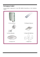
Packaging Content Actual product appearance may differ slightly depending on the hardware version.
2: Hardware Setup The access point can be powered using either the power adapter, or the PoE * or IEEE 802.3af PoE. The installation process for the three options is described below. Option 1: Using Power Adapter to Supply Power Before attaching a pair of external antennas to the access point, take note of the ‘A’ marking on one of the two antennas. Connect the single-band G antenna to Ant-2 on the RIGHT. The antenna with the ‘A’ marking is the Dualband AG Antenna.
Insert one end of the RJ45 Ethernet cable to any of the LAN ports (1, 2, 3, or 4) on the access point and the other end to your PC’s Ethernet network adapter. PC Attach the power adapter to the main electrical supply and connect the power plug into the socket of the access point. Power on your PC. Notice that the Power and the corresponding port LEDs have lighted up. This indicates that connection has been established successfully between the access point and your PC.
Option 2: Using PoE to Supply Power PoE (Power-Over-Ethernet) can be used to power the access point. This accessory supplies operational power to the wireless access point through the Ethernet cable connection and is available separately. If you wish to use PoE to supply power to the access point, follow the steps below: Follow the steps described in Option One. Connect one end of an RJ45 Ethernet cable to LAN OUT port of the PoE Injector and the other end to Port 4 of the access point.
Connect the RJ45 Ethernet cable attached to the PoE Injector to your PC’s Ethernet network adapter. Once you have finished configuring the access point, you can connect the PoE Injector’s RJ45 Ethernet cable to your network device, such as a switch or a hub. Connect the power adapter supplied in the PoE kit to the main electrical supply and the power plug into the socket of the injector. Note: DO NOT interchange the access point and PoE power adapters. The voltage and current supply is incompatible.
Turn on your power supply. Notice that the Power LEDs have lighted up. This indicates that the access point is receiving power through the PoE Injector. Notice also that the Port 4 LEDs have lighted up. This indicates that connection between the access point and your PC has been established.
3: Access to Web Interface There are 2 methods to access the web interface of the access point: 1. Access to the Web Interface Through Utility – uConfig Access the web interface directly without having to change the IP address of your PC. 2. Access to the Web Interface Through web browser 1. Assign an IP address to your PC so that it is in the same subnet as the access point. (Example: 192.168.168.xxx where x can be any value from 2 to 254) 2.
Access to the Web Interface Through Utility - uConfig The powerful uConfig utility provides convenient access to the web configuration page. Insert the Product CD into your CD-ROM drive. From the Utilities section, select to install the uConfig utility to your hard disk. After installation, double-click on the uConfig icon. The following screen will appear, click on the Yes button to proceed.
Select the access point in the products list section and click on Open Web button. To update and display the available device(s) in the list, click on the Refresh button.
This screen prompts you not to exit your uConfig program while accessing to your web interface, or else you will fail to connect to your device. Click on the OK button to proceed. At the authentication page, click on the LOGIN! button to enter the main configuration page. The default password is “password”.
You will then reach the home page of the access point web interface. Note: Refer to User’s Manual for detailed instructions on configuring the access point for wireless access. Access to the Web Interface Manually To access the web interface manually, you need to configure the TCP/IP of your PC. Refer to User’s Manual Chapter 4: Accessing the Web Interface for details.
4: Panel Views and Descriptions Front View in standing position 7 1 2 3 4 5 6 Rest feet attached to the bottom of the access point 13
Side View in standing position 7 8 9 10 12 14 11
Panel Description Name 1 2 3 4 Power (LED) WAN (Link/Activity LED) WLAN (1), (2) (Link/Activity LED) 1, 2, 3, 4 (Link/Activity/Speed LEDs) Description Steady Green Off The device is powered up. No power is supplied to the device. Steady Green Flashing Green The WAN connection is ON. Steady Green Wireless interface up and running. Ready for operation. Flashing Green Activity is detected in the wireless network. Data transmission at WAN connection.
6 Rest Feet 7 External Antennas These rest feet hold the access point in the standing position. SMA antennas 8 R232 (Integrated Serial Interface) Not in use. Reserved for future update. 9 WAN (Ethernet Port) 10/100Base-T Port connects to Cable/ADSL modem. 10 1, 2, 3, 4 (Ethernet Ports) Integrated 3-port 10/100Mbps Switching. Ports 1, 2, 3, and 4 all function as normal Ethernet ports except that Port 4 supports PoE connection.
5: Technical Specifications Safety and Electromagnetic Conformance • • • • • • • Standards FCC Part 15 SubPart B and SubPart C [for wireless module] EN 300 328-2 [for wireless module] EMC CE EN 301 489 (EN300 826) [for wireless module] EN 55022 (CISPR 22)/EN 55024 Class B EN 61000-3-2 EN61000-3-3 CE EN 60950 • IEEE 802.11a 54Mbps, 48Mbps, 36Mbps, 24Mbps, 18Mbps, 12Mbps, 9Mbps, 6Mbps, 1Mbps • IEEE 802.11b 11Mbps, 5.5Mbps, 2Mbps, 1Mbps • IEEE 802.
Network Interface WAN Interface: 1 x 10/100 Mbps LAN Interface: 3 x 10/100 Mbps Power over Ethernet: 1 x PoE Security • • • • • • • • • • 64 - bit / 128 – bit WEP WPA Personal WPA Enterprise WPA2-Personal WPA2-Enterprise WPA-Auto-Personal WPA-Auto-Enterprise Wireless Pseudo Virtual LAN IEEE 802.1x – TLS, TTLS, PEAP, EAP-SIM Stateful Packet Inspection Firewall Output Power IEEE 802.11a: IEEE 802.11b: IEEE 802.
Certifications Environment Requirements Operating Temp: Storage Temp: Operating Humidity: • • • • FCC CE Mark Gost C-tick N 12030 0ºC to 55ºC -20ºC to 75ºC 10% to 80% RH Humidity (RH – Relative Humidity): Antenna Configuration (WP18 1A) ANT-1: WLM54AG (a/b/g) card MAIN ANT-2: Antenna Configuration (WP18 2A, 2B, 2C, 3A, 3C, 3D) WLM54AG (a/b/g) card AUX ANT-1: WLM54AG (a/b/g) card MAIN ANT-2: WLM54G (b/g) card MAIN Further Information References For more details on the access point configuration,
Disclaimer: Compex, Inc. provides this guide without warranty of any kind, expressed or implied, including but not limited to the implied warranties of merchantability and fitness for a particular purpose. Compex, Inc. may make improvements and/or changes to the product and/or specifications of the product described in this guide, without prior notice. Compex, Inc will not be liable for any technical inaccuracies or typographical errors found in this guide.
WARRANTY REGISTRATION CARD [M-0088-V2.4C] Register via the Internet at http://www.cpx.com or http://www.compex.com.sg To activate the warranty, please complete this card and return to Compex within ninety (90) days from the date of purchase. Please e-mail this warranty card to support@compex.com.sg. Product: Purchase Date: Name: Model: Serial No: E-mail: Company: Address: Postal/Zip Code: Phone: ( Country: ) Note: For purchases within U.S.A and Canada, please fax to Compex, Inc.
Manual Number: M-0508-V1.3C Version 1.