© Copyright 2006 Compex Systems Pte Ltd All Rights Reserved This document contains information that is protected by copyright. Reproduction, adaptation or translation without prior permission is prohibited, except as allowed under the copyright laws. Trademark Information Compex®, ReadyLINK® and MicroHub® are registered trademarks of Compex, Inc. Microsoft Windows and the Windows logo are the trademarks of Microsoft Corp. NetWare is the registered trademark of Novell Inc.
FCC Compliance Statement This device complies with Part 15 of the FCC Rules. Operation is subject to the following two conditions: 1. This device may not cause harmful interference, and 2. This device must accept any interference received, including interference that may cause undesired operation. Declaration of Conformity Compex, Inc.
Technical Support Information The warranty information and registration form are found in the Quick Install Guide. For technical support, you may contact Compex or its subsidiaries. For your convenience, you may also seek technical assistance from the local distributor, or from the authorized dealer/reseller that you have purchased this product from. For technical support by email, write to support@compex.com.sg. Refer to the table below for the nearest Technical Support Centre.
About This Document The products described in this document, Compex Dual Band Wireless A+G VPN Internet Router, NetPassage 18A series are licensed products of Compex Systems Pte Ltd. Information provided: This document contains instructions for installing, configuring and using all two versions of the Compex NetPassage 18A series. It also gives an overview of key applications and networking concepts relevant to the products.
TABLE OF CONTENTS © COPYRIGHT 2006 COMPEX SYSTEMS PTE LTD ....................................................I TRADEMARK INFORMATION ......................................................................................I DISCLAIMER ...............................................................................................................I YOUR FEEDBACK .......................................................................................................I FCC NOTICE ....................................
How to Setup WPA Personal ...............................................................................37 ADVANCED WLAN SETTINGS ..................................................................................38 ANTENNA CONTROL .................................................................................................40 LONG DISTANCE PARAMETERS .................................................................................41 WMM ...................................................................
WEB MANAGEMENT SETUP ......................................................................................95 REMOTE MANAGEMENT ...........................................................................................97 UNIVERSAL PLUG AND PLAY (UPNP) .......................................................................98 PARALLEL BROADBAND .........................................................................................100 Load Balancing...........................................................
ACCESSING YOUR USB HARD DISK VIA WINDOWS FILE SERVER .........................165 USING WINDOWS FILE SERVER TO MAP TO NETWORK DRIVE ................................166 CHAPTER 13: WEBCAM SETUP AND VIEW ..................................................168 CONFIGURING INTERNET EXPLORER SECURITY ..........................................................168 CONFIGURING THE WEBCAM SETUP .......................................................................169 VIEWING THE WEBCAM ................................
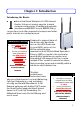
Chapter 1: Introduction Introducing the Router T His is a Dual Band Wireless A+G VPN Internet Router. It does not merely operate in wired network environments, it additionally upholds simultaneous IEEE802.11a and IEEE802.11b/g connections, as is often required in hotspots and other public Internet access deployment. Advanced Features New 54Mbps 802.11a & 802.11g 5X faster than 802.11b! Secure your wireless data transmissions with WPA protocol, IEEE 802.
Chapter 2: Getting to know your Router The following will help you get more acquainted with the rich suite of features offered by the router so that you are better able to exploit your router’s full potential. Key features Compatible with IEEE 802.11g/b and IEEE 802.11a standards Adopting the 802.11g standard, the router provides you the fastest wireless access within your office or home network. Since it is fully backward compatible with 802.11b, you can safeguard your existing network investments.
Virtual AP (Multiple SSID) Virtual AP implements mSSID (Multi-SSID) This allows a single wireless card to be set up with up to 16 virtual AP connections with different SSIDs or BSSID (Basic Service Set Identifier) and security modes. WMM WMM (Wireless Multimedia) improves the user experience for audio, video, and voice applications by prioritizing data traffic.
Security Features You will be glad to learn about the security elements we have put in place to better protect your data and privacy. WPA (Wi-Fi Protected Access) Standard & 802.1x Authentication The router supports the WPA standard for enhanced security in your wireless network. The WPA protocol combines two mechanisms: Dynamic Key Encryption and Mutual Authentication for enhanced security in the wireless LAN.
Additional Features These features reveal the comprehensive range of advanced functionalities when the router is further configured. Static IP, Dynamic IP, PPPoE, PPTP, and L2TP WAN types Whether you have subscribed to fixed IP, dynamic IP or PPPoE, you can use the router for broadband cable /ADSL Internet connection sharing. Parallel Broadband The unique Parallel Broadband technology features improved load balancing and fail-over Internet connectivity.
When to use which router NetPassage 18A IB11US, 1A13EU, IB11US, and 1B13EU are dualband wireless A+G VPN Internet router offering simultaneous support of IEEE 802.11a and IEEE 802.11g/b wireless LAN connections. NetPassage 18A 1A00US, 1A00EU, 18A 1B00US, and 1B00EU are VPN Internet routers used only in wired environments.
Panel Views The router has been designed such that it can either be placed on a desktop or mounted onto a wall. LED indicators denoting network status and activity, are situated on the front edge of the router for easy visibility. Moreover, two plastic feet support the router in a standing arrangement, thus minimising desktop clutter and ensuring better organization when setting up the hardware. NOTICE: Actual product appearance may slightly differ depending on the hardware version.
8
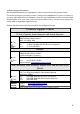
Panel Description Name 1 2 3 4 Power (LED) WAN (Link/Activity LED) WLAN (1), (2) (Link/Activity LED) 1, 2, 3, 4 (Link/Activity/Speed LEDs) Description Steady Green Off The device is powered up. No power is supplied to the device. Steady Green Flashing Green The WAN connection is ON. Steady Green Wireless interface up and running. Ready for operation. Flashing Green Activity is detected in the wireless network. Data transmission connection.
6 External Antennas SMA antennas 7 Rest Feet These rest feet hold the router in the standing position. 8 USB1, USB2 USB Ports (NP18A 1A, NP18A 2A) R232 (Integrated Serial Interface) These ports support printers, webcams, or hard drives. Not in use. Reserved for future update. 10 WAN (Ethernet Port) 10/100Base-T Port connects to Cable/ADSL modem. 11 1, 2, 3, 4 (Ethernet Ports) Integrated 3-port 10/100Mbps Switching.
13 Reset (Push Button) ! The table below illustrates the use of the Reset button. Reset Push Button Diagnostic LED Router Behavior Less than 3 sec 5 sec On Reboots. Fast Blinking Restores the default login password, which is ‘password’. Between 8 sec and 10 sec Slow Blinking Restores all the default factory settings including password. More than 10 sec Off Reset cancelled. NOTE: Although the Ethernet ports are numbered 1 to 4, they DO NOT have to be connected sequentially.
Chapter 3: Hardware Setup Before attaching a pair of external antennas to the router, take note of the ‘A’ marking on one of the two antennas. Connect the singleband G antenna to Ant2 on the RIGHT. The antenna with the ‘A’ marking is the Dualband AG Antenna. Connect the Dualband AG antenna to Ant-1 on the LEFT. ‘A’ marking The antenna without the marking is the single-band G Antenna. ! Important: To ensure proper functionality of the router, these two antennas MUST NOT be swapped.
Insert one end of the RJ45 Ethernet cable to any of the LAN ports (1, 2, 3, or 4) on the router and the other end to your PC’s Ethernet network adapter. PC Attach the power adapter to the main electrical supply and connect the power plug into the socket of the router. Power on your PC. Notice that the Power and the corresponding port LEDs have lighted up. This indicates that connection has been established successfully between the router and your PC.
Chapter 4: Accessing the Web interface This chapter consists of the following: Overview of alternatives to access the web interface How to uConfig to the web interface How to browse to the web interface Overview of alternatives The router can be configured with the web interface. After connecting the router to your PC, there are two methods of accessing its web interface: Installing and running the uConfig utility. Changing your web browser settings.
After installation, your PC will automatically detect connected products. Double-click on the uConfig utility icon to run the program. Running uConfig 1 1. Ensure that the router is selected under the Products List. 2. Click on Open Web. This opens screen. the router’s login 2 This screen prompts you not to exit uConfig while accessing the web interface or else connection to the device will fail. Click on the OK button to proceed.
How to Browse to the Web Interface Browsing to the web interface Open your Command prompt window and type in: ping 192.168.168.1 to verify that your PC can communicate with the router. If your TCP/IP settings are correct, you will get replies to this ping command. 1. 2. 3. 4. 1. At the address http://192.168.168.1 bar, Launch your web browser. Under the Tools tab, select Internet Options. Open the Connections tab. In the LAN Settings section, disable all the option boxes. type: 2.
Chapter 5: Setting Up a WLAN This chapter applies exclusively to Wireless Setup (a/b/g) and Wireless Setup (b/g). Wireless Setup (a/b/g) supports IEEE 802.11a and IEEE 802.11g/b wireless LAN connections simultaneously. Wireless Setup (b/g) supports IEEE 802.11b and IEEE 802.11g wireless LAN connections simultaneously. Whether you’re a home user or a network administrator, a WLAN implementation will allow your roaming users to enjoy network resources anywhere, anytime.
Operation Modes Access Point Mode This is the default mode of your access point. The Access Point mode enables you to bridge wireless clients to access the wired network infrastructure and to communicate with each other. In the example above, the wireless users will be able to access the file server connected to the switch through the access point in Access Point mode.
Client Mode In Client mode, the device acts as a wireless Client. When connected to an access point, it will create a network link between the Ethernet network connected at this Client device, and the wireless and Ethernet network connected at the access point. In this mode it can only connect with an access point. Other wireless clients cannot connect with it directly unless connected to the same access point - allowing them to communicate with all devices connected at the Ethernet port.
Transparent Client Mode In Transparent Client Mode, the access point provides connection with an AP acting as Root AP. This operation mode is designed for implementation of Point-to-Point and Point-to-MultiPoint connections. Point-to-Point An access point acts as Root AP and 1 other access point acts as Transparent Client. Point-to-MultiPoint An access point acts as Root AP and several other access point acts as Transparent Clients.
Difference Between other client modes and Transparent Client Mode Other client modes Connectivity with any standard APs. All devices connected to the Ethernet ports use a common MAC address for communications with the AP. Transparent Client Mode Connectivity with RootAP-supported APs. Devices connected to the Ethernet ports flow through freely and transparently without the MAC address restriction.
To Set Up a Wireless LAN Follow these steps to setup your wireless LAN for IEEE 802.11a, IEEE 802.11b, and IEEE 802.11g. WLAN Setup (a/b/g) 1 Click on WLAN Setup(a/b/g) from the CONFIGURATION menu. 2 Select Basic to make changes. If you disable the card, you will not be able to use the features of this wireless card. If you wish to disable the card, click on the Click to Disable This Wireless Card button. Click Reboot in Reboot System page. Rebooting page displays and machine reboots.
3 The router supports wireless LAN connectivity that is fully compliant with the IEEE 802.11g, IEEE 802.11a, and IEEE 802.11b standards. It also employs different security modes to secure the data transmission of the wireless clients within your network. The Current Mode is defaulted to Access Point. To change the mode, click on the Change button. 4 To change the wireless mode, make a selection from the dropdown box.
Wireless mode : Select from the list of wireless modes available: 802.11a (not supported by WLAN Setup for b/g) This mode supports wireless A clients with data rates of up to 54Mbps in the frequency range of 5.4GHz. 802.11b only This mode supports wireless B clients with data rates of up to 11Mbps in the frequency range of 2.4Hz. 802.11g only This mode supports wireless G clients with data rates of up to 54Mbps in the frequency range of 2.4Hz. Country Code : Channel : 802.
Point-to-Point & Point-to-MultiPoint Setup You can implement Point-to-Point connection by simply setting one access point as RootAP in Access Point mode and setting the other access points to Transparent Client mode. You can set a root access point and a transparent client to allow pointto-point communication between different buildings and enable you to bridge wireless clients that are kilometres apart while unifying the networks.
RootAP Step 2: Select Act as RootAP, click on the Apply button and reboot your device to let your changes take effect.
Follow these steps to setup Transparent Client/s. Transparent Client Step 1: Click on WLAN Setup from the CONFIGURATION menu. You will see the sub-menus expanded under WLAN Setup. Click on Basic. Ensure that The Current Mode is set to Transparent Client. To change The Current Mode, please refer to: Common Configuration – WLAN Setup - To Configure the Basic Setup of the Wireless Mode.
Transparent Client Step 2: Select the Remote AP MAC checkbox. Enter the Remote AP MAC. Note: When using Remote AP MAC, the ESSID name must also match the AP’s ESSID name, especially when Closed System is enabled on the AP. Repeat Transparent Client step to add more points to the Point-toMultiPoint connection.
How to Make Your WLAN More Secure All your network clients MUST share the same wireless settings as your router to be able to communicate. The router offers 8 types of security modes: WEP Short for Wired Equivalent Privacy, WEP is a security protocol basing on a secret key to encrypt data packets before they are transmitted. You MUST remember to apply the same WEP settings and key to the router as well as to all your wireless clients. 802.1x This mode conforms to the IEEE 802.
WPA2 Personal WPA2 Personal mode implements the full IEEE 802.11i standard with a shared network password for clients and access points. The only interaction is between the router and the client, therefore, a RADIUS server is NOT required. WPA2 Enterprise WPA2 Enterprise mode implements the full IEEE 802.11i standard and 802.1X authentication. There MUST be a RADIUS server on your LAN for this security mode to function.
The subsequent sections illustrate how to configure each security mode. Begin with following the two common preliminary steps shown below to select the most appropriate security mode to protect your wireless communications. Selecting a security mode 1 Click on WLAN Setup(a/b/g) from the CONFIGURATION menu. Select Security. 2 1. Make a selection from the Security Mode drop down menu. The Security Mode is disabled by default. 2. Click on Apply.
How to Setup WEP WEP 1 You can define up to 4 WEP keys. For each key, you can specify: The Key Entry Method, by selecting either: Hexadecimal ASCII text The encryption level, from the dropdown list: 64-bit 128-bit Click Edit to set the keys, and then click Apply.
2 For hexadecimal key entry: 1. Select the Hex radio button. 2. Select the radio button of the key to be entered. 3. Select the key encryption mode from the drop down menu. 4. Fill in the key value. A hexadecimal value is made of digits 0-9 and letters A-F, and is NOT case-sensitive. For 64-bit encryption: Your WEP key has to be 10 hex digits long. For 128-bit encryption: Your WEP key has to be 26 hex digits long. 5. Click on Apply. 6.
3 For ASCII key entry: 1. Select the ASCII radio button. 2. Select the radio button of the key to be entered. 3. Select the key encryption mode from the drop down menu. 4. Fill in the key value. An ASCII value can take in any alphanumeric character and is NOT case-sensitive. For 64-bit encryption: Your WEP key has to be 5 characters long. For 128-bit encryption: Your WEP key has to be 13 characters long. 5. Click on Save. 6.
How to Setup 802.1x 802.1x 1 1. Key in the IP address of the Primary RADIUS Server in your WLAN. Optional: You may also key in a Secondary RADIUS Server, if any. Note: The RADIUS server MUST be in the same subnet as your router. 2. The Authentication Port is preset as 1812, but another port number can be used. Note: The Authentication Port MUST match the corresponding port of the RADIUS server. 3. Enter the Shared Secret Key, known only to you and the RADIUS server. 4.
How to Setup WPA Enterprise Modes Follow these steps to setup the router to use WPA Enterprise, WPA2 Enterprise, and WPA Auto Enterprise. WPA Enterprise 1 1. Select the Cipher Type to implement: • TKIP • AES • AUTO The Cipher Type is set to AUTO by default so that the router can automatically detect which cipher type can be supported by the client. 2. Key in the IP address of the RADIUS Server in your WLAN. Note: The RADIUS server MUST be in the same subnet as your router. 3.
How to Setup WPA Personal Follow these steps to setup the router for using WPA Personal, WPA2 Personal, and WPA Auto Personal. WPA Personal 1 1. Fill in the Passphrase or preshared network key. 2. Select the Cipher Type to implement: a. TKIP b. AES c. AUTO. The Cipher Type is set to AUTO by default so that the router can automatically detect which cipher type can be supported by the client. 2 1. Click Apply. 2. Click Reboot to restart the system, after which your settings will become effective.
Advanced WLAN Settings Follow these steps to change the radio settings of your router. Editing Advanced Settings 1 1. Click on WLAN Setup (a/b/g) from the CONFIGURATION menu. 2. Select Advanced. 2 1. Set the Beacon Interval (the time lapse between every beacon sent) to any value between 200 and 1000. It is preset as 200 seconds. 2. Set the Data Beacon Rate from 1 to 16384.
8. 6. Select whether to enable Station Isolation. This security feature implements isolation, in order to prevent network clients from attacking other network clients. 7. The Antenna Control function allow you to control whether to use the: • MAIN antenna (Default) • AUX (Auxiliary) antenna OR • Diversity, to monitor the signal from each antenna and automatically switch to the one with the better signal. For Antenna Control recommended settings, please refer to the next section.
Antenna Control These are the recommended antenna control settings.
Long Distance Parameters It is necessary to adjust the long distance parameters, only if the distance is 100 meters and beyond. Follow these steps to change the long distance parameters of your router. Editing Long Distance Parameters 1 1. Click on WLAN Setup (a/b/g) from the CONFIGURATION menu. 2. Select Advanced. 1. Click Long Distance Parameters.
3 1. Select whether to Enable or Disable Outdoor operation. 2. Enter Distance of the unit in meters. 3. Enter the SlotTime. 4. Enter the acknowledgement timeout. 5. Enter the CTS timeout. 6. Click Apply. This dialog box displays if the Distance entered is less than 100 meters. To view recommended long distance parameters: Click Show Reference Data button.
WMM Wireless Multimedia (WMM) is a feature specially developed to improve the user’s experience for audio, video, and voice applications by prioritizing data traffic.
Follow these steps to change the setup Wireless Multimedia on your access point. Setting WMM 1 3. Click on WLAN Setup (a/b/g) from the CONFIGURATION menu. 4. Select Advanced. Click WMM Settings. 2 1. 3 Select to Enable Wireless Multimedia (WMM) 2. Enter the desired WMM parameters. Using the default parameters is recommended. 3. Click Apply to apply the WMM settings, click Default to reset all parameters to default, or click Back to discard any changes and return to WLAN Basic Setup page.
WMM Parameters (for advanced users) AIFs (Arbitrary InterFrame Space) Cwmin (Contention Window Minimum) CwMax (Contention Window Maximum) TxOp limit (Transmit Opportunity Limit) NoAck (No Acknowledgement) ACM (Admission Control Mandatory) Arbitrary Inter-Frame Space is the fixed wait time for different data traffic to access the network. Contention Window Minimum is the minimum random wait time for different data traffic to access the network.
Statistics Follow these steps to view the WLAN detailed connections statistics per WLAN station. Statistics 1 1. Click on WLAN Setup (a/b/g) from the CONFIGURATION menu. 2. Select Statistics. 2 1. Select the WLAN connection to view statistics of. • Click Refresh to refresh the WLAN Connection List. • Click Back to return to the WLAN Basic Setup page. 3 The WLAN displays. connection’s statistics Click Back to return to WLAN Basic Setup page.
Virtual AP (Multiple SSID) Virtual AP implements mSSID (Multi-SSID) whereby a single wireless card can be setup with up to 16 virtual AP connections with different SSIDs or BSSID (Basic Service Set Identifier) and security modes. Virtual AP delivers multiple services by VLAN segmentation: making the network think there are many SSIDs available and channeling each connection through different VLANs to the respective virtual network segments on the Ethernet network.
Follow these steps to setup Virtual AP. Virtual AP 1 1. 2. Click on WLAN Setup (a/b/g) from the CONFIGURATION menu. Select Virtual AP. 2 Virtual AP List page displays. • Click Apply to register changes. • Click Clear to clear Virtual AP List. • Click Back to return to WLAN Basic Setup page. • Select the Delete option beside any Virtual APs you wish to delete. Click Add to goto add Virtual AP page. 3 1. Enter ESSID name. 2. Settings: 3. 4.
Preferred APs (Only available in Client Mode) When there is more than one AP with the same SSID, the Preferred APs function allows you define the MAC address of the APs in order of preference. The MAC address at the top of the Preferred APs list has the highest connection preference, and the MAC address at the bottom has the lowest connection preference. Follow these steps to specify your preferred APs. Preferred APs 1 1. Click on WLAN Setup (a/b/g) from the CONFIGURATION menu. 2. Select Preferred APs.
Antenna Alignment The antenna alignment function helps you find the best alignment for the antenna by measuring the quality of the signal. For best results during the antenna alignment, turn off all wireless networking devices within range except the device with which you are trying to align the antenna. Follow these steps to setup your wireless LAN. Antenna Alignment 1 1. Click on WLAN Setup (a/b/g) from the CONFIGURATION menu. 2. Select Antenna Alignment. 2 1.
Chapter 6: Configuration This chapter describes the different features of your router and explains how to customise them to meet your network requirements. Setting up the router in your LAN SNMP (Simple Network Management Protocol) Setup Setting Up the Router in Your LAN The following table lists out the parameters relevant to your LAN setup. You can replace the default settings with appropriate values to suit the needs of your LAN.
the DHCP Start IP Address should be 192.168.168.X where X is any value from 2 to 254. It is preset to 192.168.168.100. DHCP End Address IP This is the last IP address that the DHCP server can assign. The value you enter should also belong to the same subnet as your router. For example if the IP address and network mask of your router are 192.168.168.1 and 255.255.255.0 respectively, the DHCP End IP Address should be 192.168.168.X where X is any value from 2 to 254. It is preset as 192.168.168.254.
Setting Up Your LAN Follow these steps to change the values and customise them for your LAN settings. LAN Setup 1 Click LAN Setup from CONFIGURATION menu. the 2 2. Amend the relevant fields in the LAN Setup page. 3. Click Apply, changes.
To view the active DHCP leases The following will guide you to a display of the active IP address leases that have been allocated by the built-in DHCP server. To view the active DHCP leases 1 1. Click LAN Setup from the CONFIGURATION menu. 2. In LAN Setup page, go to Advanced DHCP Server Options. 3. Click Show Active DHCP leases. 2 ! The DHCP Active Leases table displays: The IP Address that has been allocated to the DHCP client. The Host Name of the DHCP client.
To reserve specific IP addresses for predetermined DHCP clients The ability to make IP reservations enables you to assign a fixed IP address to a predetermined client (identified by its MAC address), thus informing the DHCP server to exclude that specific address from the pool of free IP addresses it draws on for its dynamic address allocation.
3 If you do not need the DHCP server to reserve an IP address anymore, you can delete the DHCP Server Reservation: 1. Select the reserved IP address to delete. 2. Click Delete. 3. The DHCP Reservations table will refresh to reflect the changes.
Bandwidth Control for WAN Bandwidth Control allows you to decide the available bandwidth in levels of 1kbit. Follow these steps to setup Bandwidth Control for WAN. Bandwidth Control for WAN 1 Click Bandwidth Control CONFIGURATION menu. from the 2 Select whether to Enable or Disable Bandwidth Control and click Apply. 3 To apply Bandwidth Control on WAN, in WAN Bandwidth Control Setup: 1. Enter the Download Total Rate in kbit. This restricts the bandwidth available for downloading. 2.
Bandwidth Control for LAN Bandwidth Control allows you to decide the available bandwidth in levels of 1kbit. Follow these steps to setup Bandwidth Control for LAN. Bandwidth Control for LAN 1 Click Bandwidth Control CONFIGURATION menu. from the 2 Select whether to Enable or Disable Bandwidth Control and click Apply.
3 1. Enter the Bandwidth Control Rule Name. 2. Enter the Committed Rate in kbit. This sets the bandwidth committed. 3. Enter the Ceil Rate in kbit. This is the ceiling rate which sets the maximum bandwidth allowed. 4. Enter the Rule Type Rule Types: • Download by IP Address • Download by MAC Address • Upload by IP Address • Upload by MAC Address 5. Enter the IP or MAC Address according to the Rule Type selected. 6.
STP Setup Spanning Tree Protocol is a link management protocol that provides path redundancy while preventing undesirable loops in the network. For an Ethernet network to function properly, only one active path can exist between two stations. Multiple active paths between stations cause loops in the network. If a loop exists in the network topology, the potential exists for duplication of messages. When loops occur, some switches see stations appear on both sides of the switch.
Priority: Specify the priority given to the AP. This value determines which access point acts as the central reference point, or Root AP, for the STP system — the lower the priority value, the more likely the access point is to become the Root AP. If the priority values are all the same, then the system will search for the access point with the smallest MAC address and set it as the Root AP.
SNMP Setup SNMP (Simple Network Management Protocol) is a set of protocols that facilitates the exchange of management information between network devices. It enables network administrators to manage network performance, detect and solve network problems, and plan for network growth. Follow these steps to setup SNMP. SNMP Setup 1 Click SNMP Setup System Tools menu. from the 2 3. From the SNMP drop-down list, select Enable.
SNMP Trap The SNMP Trap provides notification of significant network events through unsolicited SNMP messages. This results in substantial savings of network resources by eliminating the need for unnecessary SNMP requests. Follow these steps to setup SNMP Trap. SNMP Trap 1 Click SNMP Setup from CONFIGURATION menu. the 2 1. Select whether to Enable or Disable the SNMP Trap. 2. Enter the Trap Destination IP Address or Name. This is the IP address of the SNMP manager. 3. Enter the Community.
Chapter 7: Enabling and Disabling Router This chapter describes the switching capability of the unit to operate either as a router or access point. Setting Up Router By default, the unit is operating as a router. The simple procedure to enable the router is described. Enable Router Click Enable Router CONFIGURATION menu. 1 2 from the The Enable Router Function appears. Click on the Enable Router button.
Setting Up Access Point Follow these steps to disable the router and switch back as an access point. Disable Router 3 1 Click WAN Setup CONFIGURATION menu. 2 Click Disable Router. from the The Disable Router Function screen appears. Click Disable Router again.
Chapter 8: Router Setup This chapter describes the different features of your unit when it is set to operate as a router. Broadband Internet Using NAT Routing Remote Management Parallel Broadband DDNS (Dynamic Domain Name System) Setup Features unsuitable for office network: Universal Plug and Play DNS (Domain Name System) Redirection ! NOTE: Universal Plug and Play and DNS Redirection features are not designed for operation in an office network.
WAN Setup The configuration for each type of broadband Internet connection is shown in the following individual sections. The system has to be restarted to effect changes in settings. Start with these common steps to set the broadband connection type. Changing the WAN Type 1 Click WAN Setup CONFIGURATION menu. from the The setup page of the WAN type last implemented will be displayed.
Static IP If you have subscribed to a specific IP address or to a fixed range of IP addresses from your ISP, follow these steps. Static IP Configuration 1 Select Static IP Address from Select WAN Type page and click Apply. 2 At the Static IP WAN Setup page: 1. Enter the IP Address, Network Mask, and Gateway IP Address provided by your ISP. 2. Click Apply. 3. Click Reboot System to restart the system and let the changes take effect.
Dynamic IP This is the default WAN Type of your router. In this connection mode, your ISP will automatically assign its IP address. This connection mode applies to most cable Internet subscribers, for instance: Singapore Cable Vision subscribers. @HOME Cable Service users. Follow these steps to setup Dynamic IP. Dynamic IP Configuration 1 Select Dynamic IP Address as WAN Type. 2 At Dynamic IP WAN Setup page: 1.
PPPoE Select this connection type if you have subscribed to ADSL in a country utilising standard PPPoE for authentication, for instance: If you are in Germany, which uses T-1 connection. If you are a SingNet Broadband or Pacific Internet Broadband user in Singapore. These are the parameters in the PPPoE setup. PPPoE Parameter Description Username This refers to your broadband account username. Password This refers to your broadband account password.
Follow these steps to setup PPPoE. PPPoE Configuration 1 Select PPP over Ethernet from the Select WAN Type menu. 2 At the PPPoE WAN Setup page: 1. Enter your broadband Internet account parameters in the relevant fields. 2. The Status section displays connection settings such as: IP Address Network Mask Gateway IP Address Primary & Secondary DNS 3. If you are online, clicking Disconnect will disconnect your connection. 4. Click Apply. 5.
PPTP The Point-to-Point Tunneling Protocol (PPTP) enables the implementation of secure multi-protocol Virtual Private Networks (VPNs) through public networks, enabling secure remote access at lower cost. Follow these steps to setup PPTP. PPTP Configuration 1 Select PPTP as your WAN Type at Select WAN Type page. 2 At the PPTP WAN Setup page: To use Email Notification, please refer to Chapter 8: Router Setup – Broadband Internet Through the router – WAN Setup Email Notification 1.
L2TP L2TP (Layer 2 Tunneling Protocol) is an extension to the PPP protocol used for Virtual Private Networks (VPNs) that supports multiple protocols and unregistered and privately administered IP addresses over the Internet. Follow these steps to setup L2TP L2TP Configuration 1 Select L2TP as your WAN Type at Select WAN Type page. 2 At the WAN L2TP Setup page: 1. 2. 3. 4. 5. Select whether to enable DHCP. Enter Client IP Address. Enter Network Mask. Enter the Gateway.
Email Notification This feature notifies you by email if there is a change in the WAN IP address. Follow these steps to setup Email Notification. Email Configuration 1 After applying WAN PPPoE Setup, WAN PPTP Setup, or L2TP. The WAN Setup screen of the WAN Type displays. (PPPoE shown in this example. Click Email Notification. 2 Click Enable and enter the following fields: Email address of Receiver: The email will be sent to this address.
Email address of Sender: This is the email address that will appear as the sender. Needs Authentication specifies whether the SMTP server requires authentication, and is not selected by default. Click Apply.
Using NAT NAT (Network Address Translation) functions by transforming the private IP address of packets originating from hosts on your LAN so that they appear to be coming from a single public IP address, and by restoring the destination public IP address to the appropriate private IP address for packets entering the private network. The multiple PCs on your LAN would then appear as a single client to the WAN interface. Enabling/Disabling NAT NAT 1 Click NAT from CONFIGURATION menu.
When NAT is enabled, your LAN is not accessible to the WAN. However, implementing virtual servers allows you to host Internet servers such as web servers, FTP servers or Mail servers on your LAN, in spite of NAT. To Setup a De-Militarised Zone Host If NAT is enabled, a request from the client within the private network first goes to the access point. Upon receiving a request, the access point keeps track of which client is using which port number.
DMZ 1 1. Click NAT from the CONFIGURATION menu. 2. Ensure that NAT Status is set to Enable. At the Advanced NAT Options section: 3. Click DMZ. 2 1. In the Private IP Address field, enter the IP address of the PC you wish to place within the DMZ. Private IP Address is set to 0.0.0.0 by default. 2. 3 To disable DMZ: 3. In Private IP Address field enter 0.0.0.0. 4. ! Click Apply. Click Apply. NOTE: 1.
To Setup Port Forwarding Port forwarding allows the router to redirect any incoming Internet request bearing a public IP address to a specific PC on your LAN, based on the incoming packet’s TCP/UDP port number. Hence, using TCP port forwarding, you can hide your web-server behind the access point for added security, while UDP port forwarding lets you run a secure multiplayer game server. The following diagram shows a router with a public IP address of 203.120.90.3 and a private IP address of 192.168.168.1.
Follow these steps to setup port forwarding. Port Forwarding 1 1. Click NAT from the CONFIGURATION menu. 2. Ensure that NAT Status is set to Enable. At the Advanced NAT Options section: 3. Click Port Forwarding.
2 The Port Forward Entries table displays the list of current port-based entries. Click Add. 3 For standard server applications (HTTP/FTP/POP3/Netmeeting), go to Known Server: 1. Enter the Private IP Address. 2. Pick the appropriate Server Type. 3. Enter the range in the From: and To: fields. 4. Click Add. To set up Internet applications not included under Known Server, go to Custom Server: 1. Enter the Private IP Address. 2. Define the Port numbers to use. 3.
NAT Static Port Based Entries reflects the new entry. 4 To assign more servers in your LAN: 1. Click Add. This will bring you back to Add New NAT Port-Based Entry. 2. Repeat Step 3 above. To delete table entries: 1. Select the entry to delete. 2. Click Delete. The table will refresh.
The following is a non-exhaustive list of well-known port numbers: Application Echo Daytime FTP SMTP (Simple Mail Transfer, i.e.
IP Forwarding If you have subscribed to more than one IP address from your ISP, you may define Virtual Servers based on their IP address so that incoming Internet requests are forwarded to specific computers within the private network. Assuming you subscribe to the range of Public IP addresses 203.120.12.1 to 203.120.12.62 from your ISP and the PC hosting a server has a LAN IP address of 192.168.168.100: To define the Internet Server as having an IP address of 203.120.12.
3 1. Enter the Private IP Address of your virtual server as identified in your LAN. 2. Enter the Public IP Address of the server, as known outside your LAN. 3. Click Add. 4 NAT Static IP Address Entries reflects your new entry. To assign more servers in your LAN: 1. Click Add. This will bring you back to Add New NAT IP Address Entry. 2. Repeat Step 3 above. To delete table entries: 1. Select the entry to delete. 2. Click Delete. The table will refresh.
Routing The router supports both static routing for manual routing table entry addition, and dynamic routing for automatic routing table update. ! NOTE: The default settings of the router allow broadband Internet sharing so there is no need to configure any further routing information. Improper routing settings might cause improper functioning. The following diagram illustrates a wireless LAN having subnet 192.168.168.0 in which a router (X) with IP address 192.168.168.
Static Routing Follow these steps to add entries to your access point’s routing table for rerouting of IP packets to another network. Static Routing 1 Click Routing from CONFIGURATION menu. the 2 The IP Routing Table displays the list of current routing entries. To add static route in the IP Routing Table click Add. 3 1. Enter the Destination IP Address of your new entry. 2. Enter the Address. 3. Click Apply. Gateway IP The new entry will appear in the IP Routing Table.
4 The IP Routing Table reflects the new entry. To add more routes: 1. Click Add. This will bring you back to Add IP Route GUI. 2. Repeat Step 3 above. To delete a route: 1. Select the entry to delete. 2. Click Delete. The table will refresh.
Telnet/SSH Setup Telnet allows a computer to remotely connect to the CLI (Command Line Interface) for control and monitoring. SSH (Secure Shell Host) establishes a secure host connection to the CLI for control and monitoring.
Follow these steps to setup Telnet/SSH. Telnet/SSH Setup 1 Click Telnet/SSH Setup from the Device Access Management menu. 2 1. 2. 3. To enable Telnet Server: Select Telnet Server Enable and enter the Port Number. To enable SSH server: Select SSH Server Enable and enter the Port Number. Click Apply.
TELNET CLI Telnet CLI (Command Line Interface) The user may connect to the CLI (Command Line Interface) via a TELNET session to the default IP, 192.168.168.1. This section uses Microsoft TELNET command for instruction. You may use any TELNET client. Connecting to CLI (Command Line Interface) via TELNET 1. Connect to CLI (Command Line Interface) with the following command at DOS prompt. The TELNET application will then be launched and connected. C:\WINDOWS\TELNET 192.168.168.
SSH CLI SSH CLI (Secure Shell Host Command Line Interface) SSH is designed and created to provide the best security when accessing another computer remotely. Not only does it encrypt the session, it also provides better authentication facilities and features that increase the security of other protocols. It can use different forms of encryption and ciphers. The first diagram below shows a telnet session. The second diagram below shows how an encrypted connection like SSH is not viewable on the network.
SSH CLI has a command line interface like shown below for example. NOTE Please refer to Appendix D for the list of commands available at the console.
User Management User Management Click User Management from the Device Access Management menu. 1 2 To add user: 1. Click Add button. 2. In Add User Entry Page, enter User Name, Password, Confirm Password, specify whether to allow Telnet/SSH, and specify whether user is granted permission to Read Only or Read/Write. 3. Click Apply. To Delete User: 1. Select which user to Delete. 2. Click Delete. User Management list refreshes to update users.
Web Management Setup HTTPS (SSL) is supported in addition to the standard HTTP. HTTP (SSL) features additional authentication and encryption for secure communication. Follow these steps to setup web management. Web Management Setup 1 Make selection from the Device Access Management menu. 2 1. Select whether to set web server to HTTP or HTTPS (SSL) mode. 2. Click Apply.
3 Web service restarts automatically. Web session logouts. You may reconnect using the new web service using the relogin link displayed on the IP address or Web Mode changed page.
Remote Management This feature is especially helpful for users who work away from the office or from home. The user only requires Internet access to manage the network. Remote Management 1 Click Remote Management from the Device Access Management menu. 2 1. Specify the HTTP / HTTPS Port number. Note: Entering 0 would disable this feature. 80 is the default remote HTTP port. 443 is the default remote HTTPS port. 2. Click Apply. 3. Click Reboot to reboot the system to effect the changes.
Universal Plug and Play (UPnP) The following are issues that can arise when using NAT: • Some network applications assume the IP address and port that the client has been assigned are global routable values that can be used on the Internet directly. Often, this is not the case as the client has been assigned a private IP address that can only be used on the LAN.
Although NAT traversal does not solve all NAT-related issues, it allows several applications to run behind NAT-enabled devices. It is recommended that you enable UPnP when running: Multi-player games Peer-to-peer connections Real-time communications Remote Assistance • • • • UPnP 1 Click UPnP Configuration from the Configuration menu. Universal Plug and Play (UPnP) is disabled by default. 2 1. Select Status. the appropriate UPnP 2. Click Apply. 3.
Parallel Broadband Exclusive! The router is equipped with the exclusive Parallel Broadband technology, which features scalable Internet bandwidth, Load Balancing, and Fail-Over Redundancy. As there is no restriction to the type of broadband Internet account the router can connect to, your network can run with one router on Cable Internet, with the rest connected to ADSL at the same time.
To Enable Parallel Broadband Parallel Broadband can be implemented when: More than one access point is interconnected (LAN port to LAN port) in your network. Each access point is connected to a broadband Internet account. Parallel Broadband 1 Click Parallel Broadband from the CONFIGURATION menu. Parallel Broadband is disabled by default. 2 1. Enable Status. the Parallel Broadband 2. Click Apply. 3. Repeat this for the other access points in your network.
Static Address Translation (Only supported by Wireless Routing Client and Gateway) If you use a notebook for work at the office, it is probable that you also bring it home to connect to the Internet and retrieve emails or surf the web. Since it is most likely that your office’s and your home’s broadband-sharing network subnets are differently configured, you would have to struggle with reconfiguring your TCP/IP settings each time you use the notebook in a different place.
1 Under the Home User Features command menu, click on Static Address Translation. 2 You may then choose to Enable or Disable Static Address Translation here, followed by clicking the Apply button.
DNS Redirection DNS Redirection allows you to redirect DNS requests to a local or closer DNS server. This improves the response time and enables true plug-andplay accessibility, especially if your DNS server is behind a firewall or is situated on your private LAN. DNS Redirection 1 Click DNS Redirection from the Home User Features menu. 2 DNS redirection is disabled by default. 1. 2. Set DNS Redirection status to enable. Click Apply.
Dynamic DNS Setup It is difficult to remember the IP addresses used by computers to communicate on the Internet. It gets even more complicated when ISPs change your public IP address regularly, as is the case when the Internet connection type is Dynamic IP or PPPoE with Dynamic IP. If you are doing some web hosting on your computer and are using Dynamic IP, Internet users would have to keep up with the changing IP address before being able to access your computer.
3 To add a new Dynamic DNS to the list, click Add. Choice DDNS Provider page displays. There are two default providers that you can use. The parameters are explained below: Choice: This allows you to select your preferred DDNS provider. Provider Name: This is the name of your preferred DDNS provider. Register Now: This allows you to go to the website of your preferred DDNS provider to register your account.
There are two predefined DDNS providers. Please note that you need to be connected to the Internet to register your DDNS account. To select 2MyDNS – Dynamic DNS Service Provider as DDNS Service Provider 1 Under the Choice column in the Choice DDNS Provider check the radio button for 2MyDNS – DNS Service Provider. Click Next. 2 At the Dynamic DNS Add page: 1. 2. Enter your Domain Name. Select Auto Detect to detect your current WAN IP address. Enter your DDNS account Username and Password.
4 Optional: In the Mail Exchanger field, enter the Static WAN IP address of the mail server configured to handle email for your domain. Select Backup Mail Exchanger to enable this service. Click Add button to save the new addition. 5 Dynamic DNS list table displays the new domain. 6 It will appear as a hyperlink to the Dynamic DNS Edit page. From this page, you can update any of the parameters, delete the domain name, or reset all parameters.
To select DtDNS as DDNS Service Provider 1 Under the Choice column in the Choice DDNS Provider check the radio button for DtDNS. Click Next. 2 At the Dynamic DNS Add page: 1. Enter your Domain Name. 2. Select Auto Detect to detect your current WAN IP address. Enter your DtDNS account Username and Password. 3. Click Add. 3 Example: While the new domain name, cool.3d-game.
Chapter 9: Security Configuration The Security Configuration chapter covers: Firewall Configuration Firewall Logs Packet Filtering URL Filtering Multicast Filtering The router makes use of Packet Filtering and Stateful Packet Inspection (SPI) to examine each message entering or leaving your LAN and block those that do not satisfy your specified security criteria.
Firewall Configuration Follow these steps to configure the firewall. Firewall Configuration 1 Click Firewall Configuration from the Security Configuration menu. 2 1. Enable the firewall. You can choose the Default Low, Default Medium, or Default High security options for convenient setup. 2. Choose the type of network activity information to log for reference. Data activity arising from different types of protocol can be recorded. 3.
More firewall rules can be added for specific security purposes. Rule Name : Disposition : Policy Enter a unique name to identify this firewall rule. This parameter determines whether the packets obeying the rule should be accepted or denied by the firewall. Choose between Accept, or Deny. Protocols : Users are allowed to select the type of data packet from: TCP, UDP, ICMP, IGMP, or ALL.
congestion. Redirect Informs the host of a preferred route. Time exceeded Indicates that the Time-to-Live (TTL) of an IP datagram has expired. Parameter Informs that host that there is a problem in Problem one the ICMP parameter. Timestamp Information that is from the ICMP data Request packet. Information Information that is from the ICMP data Request packet. Information Reply Information that is from the ICMP data packet.
available selection options are abbreviated as follows: SEC – Security LSRR – Loose Source Routing Timestamp – Timestamp RR – Record Route SID – Stream Identifier SSRR – Strict Source Routing RA – Router Alert Check TTL : This parameter would let you screen packets according to their Time-To-Live (TTL) value available options are: 1. Equal 2. Less than 3. Greater than 4.
3 1. Rule Number ranges from 1 to 40. Precedence is determined in ascending order such that rule 1 takes precedence over rule 2. 2. Select whether to Deny or to Accept packets for the Disposition Policy. 3. Pick the relevant Protocol. 4. For ICMP Types, select the checkboxes according to the ICMP information for the gateway to discard/collect. 5. Similarly, the IGMP Types section lets you choose which IGMP packets to discard/ record. 6.
9. Similarly, determine Destination Port. the 10. Select from Check Options. 11. Select whether to log packets of TTL Values Equal, Less, Greater, or Not Equal to the defined TTL value. 12. Enter TTL value. 13. Click Apply settings. ! to apply NOTE: Up to 40 firewall rules can be defined, with precedence determined by the rule number. For example: If Rule 5 blocks all ICMP packets in your LAN, but Rule 6 authorises ICMP-Redirect packets in the LAN, the ICMP Redirect packets will still be blocked.
Firewall Logs As described previously, from the Firewall Configuration page the data traffic to be logged by the router can be defined. The Firewall Log also records any UDP flooding or SYN flooding attacks on your network. Firewall Logs 1 Click Firewall Logs from the Security Configuration menu. 2 1. A firewall log entry consists of: Time at which the packet was detected by the firewall. Action, which states whether the packet was accepted or denied. Protocol type of the packet.
Packet Filtering With Packet Filtering enabled, the router examines all outgoing packets before deciding - according to predefined rules - whether to block them or to let them pass. The setting of rules to control the network user access should be done by the system administrators.
Follow these steps to setup packet filtering. Packet Filtering 1 Click Packet Filtering from the Security Configuration menu. 2 Clicking Change select Packet Filter Type. 3 Select from three choices: Disabled, Sent, Discarded, then click Apply. The default is Disabled, allowing all packets to be sent. ` 4 Click Add. The following steps guide you through the packet filter rules that can be defined on this page. 4a). Enter Rule Name of the new packet filtering rule.
4b). From the IP Address dropdown list, select whether to apply the rule to: A Range of IP addresses. Define (From) which IP address (To) which IP address, the rule applies. A Single IP address. You need only specify the source IP address in (From). Any IP address Both (From) and (To) may be left blank. 4c). From the Destination Port dropdown list, select whether to apply the rules to: A Range of IP addresses. Define (From) which IP address (To) which IP address, the rule applies. A Single IP address.
MM can take any value from 00 to 59. Any time Both (From) and (To) may be left blank. Click Apply, to apply the new rule. The Filtering Configuration table updates. In this example, the rule BlockCS blocks any IP address (any PCs within the network) from an application using port 27015 from Monday to Friday, 7am to 6pm.
URL Filtering The URL Filtering feature of the router makes it easy to block certain websites from LAN users. URL Filtering 1 Click URL Filtering from the Security Configuration menu. 2 The URL Filter Type can be defined by clicking Change. Selecting Block Select Block or Allow, then click Apply. The default is Disabled, allowing all websites to be accessed. Click Add.
Selecting Allow 3 In Host Name, enter the web site address to be blocked. For example: www.objectionablewebsites.com Click Add to complete setup.
Multicast Filtering This feature lets you allow or disallow streaming over the Internet, if you have registered to ISP services providing videos and TV channel streaming. Multicast Filtering 1 Click Multicast from Configuration menu. the Security 2 Enabling video the filter streaming disallows over the Internet whereas disabling the filter would allow it. Click Apply to complete setup. Note: This feature is enabled by default.
Chapter 10: Web Interface Utilities This chapter describes the use of: The System Tools menu The Help menu Using the SYSTEM TOOLS Menu Ping Utility The Ping Utility works like the commonly used Ping.exe program in Command Prompt. It allows pinging of IP addresses or domain names. Follow these steps to use the Ping Utility. Ping Utility 1 Click Ping Utility from the System Tools menu. 2 Enter the Target Host IP Address or Domain Name and click Start to begin pinging.
3 The Ping Utility pings the target with 10 packets of 56 bytes data and displays the results and statistics at the end. Click Back to return to the previous Ping Utility page.
Syslog Syslog allows remote system logging. You can setup Syslog with the following steps. Step 1: Click on Syslog from the SYSTEM TOOLS menu. Step 2: Select to Enable Syslog. Step 3: Enter the Remote IP Address or Domain Name Step 4: Enter the Remote Port Step 5: Click Apply to make the changes.
To Identify Your System If your network operates with several of the access points, a means of identifying each individual access point would be useful. In certain cases your ISP might request identification before dynamically allocating an IP address. The System Name of the router can then serve as a DHCP Client ID during negotiations with the DHCP Server of your ISP. You can define the System Identity to be utilised as System Name, or as DHCP Client ID.
Setting the Time of Your System Synchronising the clocks of the router and your workstation enables effective management and operation of the provided time-based functions. ! NOTE: The clock setting will be enabled if the unit is set to operate as a router. Follow these steps to set your system’s clock. System Clock Setup 1 Click System Clock Setup from the System Tools menu. 2 Choose the correct time zone and Enable the Auto Time Setting (SNTP) such as using a timeserver time.nist.gov Click Apply.
To Upgrade the Firmware Version The products are designed for upgradability. Click About System from the HELP menu to check your current firmware version. Firmware Upgrade 1 Click Firmware Upgrade from the System Tools menu. 2 Ensure that the latest firmware has been downloaded onto your local hard disk drive. 1. Enter the path and file name of the downloaded file in Upgrade Firmware (path and file name). Alternatively, click locate the file. Browse to 2. Click Upgrade. 3.
Settings Profile A profile is the set of parameters with which the router is configured. You may choose to: Save your customised profile Make a backup of a profile onto your hard disk Restore a profile saved on file earlier Return the access point to its default settings Follow these steps to proceed. Save or Reset Settings 1 Click Backup or Reset Settings from the System Tools menu. 2 To save current profile: 1. Click Save. 2. Restart system to ensure the right profile is being used.
Backup To return system to earlier configuration using backup file: 1. Click Browse to search for backup file. Or enter file path name in Restore the Machine’s configuration (path and file name). 2. Browse Click Restore. To discard ALL configurations made and restore the router to factory settings: 1. Click Clear and Reset. 2. Click yes when confirmation menu displays. 3. The router will restart and reload default profile. Note: Login password will revert to default.
To Reboot Most changes in system settings require rebooting to take effect. Follow these steps to reboot the router. Reboot System 1 Click Reboot AP from System Tools menu. the 2 You will be prompted to confirm reboot. Click yes to reboot the router. ! NOTE: Reboot AP or Reboot Router is displayed under System Tools depending on whether the unit is set as access point or router.
Change Your Login Password The login password is required to access the web configuration interface, through which the router’s settings can be monitored Follow these steps to change password. Change Password 1 Click Change Password from the System Tools menu. 2 Note: Password is case-sensitive. 1. Enter Current Password. The default is password 2. Enter the new password in New Password and Confirm Password. 3. Click Apply.
To Logout Follow these steps to logout. Logout 1 Click Logout from the System Tools menu. 2 A login prompt displays.
Using the HELP Menu To Get Technical Support This page contains the contact information of technical support centres around the world. Follow these steps to access the page: Get Technical Support 1 Click Get Technical Support from the HELP menu. 2 If further information is required, please contact a Technical Support Centre by email, mail, phone, or fax.
About Your System The About System page displays a summary of system configuration information that might be required by support technicians during troubleshooting. Follow these steps to view the settings. About System 1 2 Click About System from the HELP menu. The System Information page displays a summary of the router’s setup parameters.
Chapter 11: Printer Server Setup (For NP18 1A, 2B) The router can also act as a network print server that is easy to operate. When its print server functionality is enabled, you can print from any wired or wireless computer on the network to the USB printer(s) connected to the router. ! NOTE: You need to install the printer driver software (provided by the printer manufacturer) onto all the PCs in the network that will share the USB printer.
Next to add the printer to your PC: 1. Go to the Windows Start Menu; select Settings, then followed by Control Panel. 2. Then double-click Printers and Faxes. Select the Add a printer and the Add Printer Wizard appears. 3. Click Next> to proceed. 4. Check the radio button next to the Local printer attached to this computer and click Next> to proceed. Please note that you should not select Automatically detect and install my Plug and Play printer. Next to select the printer port for your PC: 1.
4. When the Add Standard TCP/IP Printer Port Wizard appears, click on the Next> button to proceed. 5. Enter your router’s IP address in the Printer Name or IP Address field. Then the corresponding Port Name will be automatically entered. 6. Click on the Next> button to proceed. 7. Go to the Device Type section and select Custom. Next to the Custom radio button, click on the Settings button. This brings out the Configure Standard TCP/IP Port Monitor window.
8. Go to the Protocol section and select LPR. 9. Next proceed to the LPR Settings section. In the Queue Name field, key in ‘usb0’. Please take note that ‘usb0’ is an example. The appropriate queue name should be derived from the URL of the printer that connects to the router. 10. Click on the Next> button to proceed. 11. After you have successfully configured the selected port, you will see the information display in this window. Click Finish to complete the port configuration.
3. 4. Then you will be prompted to choose whether to keep the existing driver or install a new driver. However, it is recommended that you should choose to keep the existing driver. Click on the Next> button to proceed. 5. Key in the printer’s name. 6. Click on the Next> button to proceed. 7. If you want to share the printer with other PC users, click the radio button next to Share name. Then key in the share name so that the users will find this name to access the shared printer.
9. It is recommended to test the printer. To print the test page, click Yes. When you get the test print out, it means that the printer is successfully installed. 10. Click on the Next> button to proceed. 11. This window displays a summary of the settings of the printer that is successfully installed. 12. To exit the window, click Finish.
Adding A Shared Printer Via LPR in Windows 2000 For Windows 2000 Users Under the HOME USER FEATURES command menu, click on Printer Server Setup. 1. Simply choose Enable or Disable for the Status of Printer Server. 2. Click on the Apply button. 3. When you connect the printer the USB port of the router, printer will be automatically displayed in the Printer List. Next to add the printer to your PC: 1. Go to the Windows Start Menu; select Settings, then followed by Control Panel. 2.
5. Check the radio button next to the Local printer attached to this computer and click Next> to proceed. Please note that you should not select the Automatically detect and install my Plug and Play printer. Next to select the printer port for your PC: 1. Check the radio button next to the Create a new port. 2. Then select Standard TCP/IP Port for the type of port you will be using. 3. Click on the Next> button to proceed. 4.
5. Enter your router’s IP address in the Printer Name or IP Address field. Then the corresponding Port Name will be automatically entered. 6. Click on the Next> button to proceed. 7. Go to the Device Type section and select Custom. Next to the Custom radio button, click on the Settings button. This brings out the Configure Standard TCP/IP Port Monitor window. 8. Go to the Protocol section and select LPR. 9. Next proceed to the LPR Settings section.
11. After you have successfully configured the selected port, you will see the information display in this window. Click Finish to complete the port configuration. Next to install the printer’s driver to your PC: 1. If you cannot find the printer’s name in the list, click Have Disk…. Then you need to install the driver manually. 2. Click on the Next> button to proceed. 3. Then you will be prompted to choose whether to keep the existing driver or install a new driver.
5. Key in the printer’s name, you can make it as the default name. 6. Click on the Next> button to proceed. 7. If you want to share the printer with other PC users, click the radio button next to Share name. Then key in the share name so that the users will find this name to access the shared printer. Otherwise if you choose not to share the printer, select Do not share this printer. 8. Click on the Next> button to proceed. 9. It is recommended to test the printer.
11. This window displays a summary of the settings of the printer that is successfully installed. 12. To exit the window, click Finish.
Adding A Shared Printer Via LPR in Windows 98/ME Before setting up the LPR printer server, you have to download the software of the LPR printer client from the website: http://www.columbia.edu/acis/access/printing/winME_files/instlpr.exe Please note that the version of the downloaded software should be V3.4f.
3. The Add Printer Wizard (shown on the left) appears. 4. Click Next> to proceed. 5. Click the radio button next to Local Printer. Then click Next> to proceed. Next to Install the printer’s driver to your PC: 1. Select the printer’s name available in the Manufacturers: and Printers: listboxes. 2. But if you cannot find the printer’s name in the list, click Have Disk…. 3. Click Next> to proceed.
4. At the Install From Disk screen, click Browse... to search for your printer’s driver and install it. 5. The Open screen prompts you to select the file name of your printer’s driver. Then click OK to proceed. When your printer’s driver is added to the Printers list, click Next> to proceed.
6. Then you will be prompted to choose whether to keep the existing driver or install a new one. But you are advised to keep the existing driver. 7. Click Next> to proceed. 8. Select LPT1 from the Available ports: list box that you want to use for your printer. 9. Click Next> to proceed. 10. Just leave the supplied fields intact as they are. Click Finish without editing anything unless required. 11. Wait for a while until the message “Setup is complete” is prompted.
12. Right-click on the icon of the printer you have just installed to select Properties. 13. At the Details tab of the printer’s properties screen, click Add Port. 14. The Add Port screen is displayed to let you select Others. 15. Below the Others radio button, highlight and select ACITS LPR Remote Printing for the type of port. To confirm the addition, click OK. 16. Then the ACITS LPR Remote Printing screen pops up.
17. At the Settings tab of the ACITS LPR Remote Printing screen, key in the router’s IP address. Proceed to key in the printer/queue name. For example, ‘usb0’ is the name derived from the URL of the printer connected to the router. For example,http://192.168.168.27:631/ printers/usb0. 18. To check if the selected printer is connected to the router or not, click Verify Printer Information. 19. At the Spool Settings screen, click the radio button next to Start printing after last page is spooled. 20.
Removing the Shared Printer from the Router Removing Printer To physically remove the network printer from the router safely, Click on the Remove button and the system will prompt whether you really want to remove the USB device from the router. Click Yes to confirm. You will then be able to safely disconnect your printer from the USB port of the router.
Chapter 12: USB Storage Disk Sharing (For NP18 1A, 2B) The router connects to your USB hard disk/flash disk to allow easy storage sharing in the network and across the Internet. Once your USB hard disk/flash disk is connected to your router, you can access the shared disk via FTP or Windows networking. ! Note: The router lets you share entire drives instead of individual folders. Enable FTP or Windows networking Under the HOME USER FEATURES command menu, click on USB Storage Disk Sharing.
Allow Anonymous: Selecting Yes indicates that you allow users to access to your USB storage disk to upload and/or download files without having to key in a username and password. Otherwise, you can create a file server account to allow only users with authorized username and password to use the file server to access your storage disk. Refer to page 88 for instructions on how to access your storage disk from Windows networking.
Advanced USB Disk Sharing Functions: Show Connections of Server Under the Advanced USB Disk Sharing Functions, click on Show connections to USB storage disk. This screen displays the number of users connected to the storage disks. Available connections: It is the maximum number of connections that the router can handle. Current: This column allows you to monitor the number of active connections established using FTP and Windows networking.
Advanced USB Disk Sharing Functions - FTP Server User Account List Under the Advanced USB Disk Sharing Functions, click on Manage FTP user account. This screen will display the list of FTP user accounts. After clicking on Add, the Add a new FTP Account screen appears. This screen allows you to create FTP user accounts so that when you set Allow Anonymous to ‘No’, only authorized users who login with the correct username and password will be able to FTP to the USB disk connected to your router.
If you wish to delete an existing or current FTP user account, go to the FTP Account Configuration page. Then click on the hyperlink next to its corresponding user name you have selected. This screen below lets you click on the Delete button to delete the user account.
Advanced USB Disk Sharing Functions - File Server User Account List Under the Advanced USB Disk Sharing Functions, click on Manage file server user account. The File Server Account Configuration screen will display the list of users who are using the file server. After clicking on Add, the Add a new File Server Account screen appears.
If you wish to edit an account password or delete a user account, go to the File Server Account Configuration page. Then click on the corresponding user name. Modify the account password and press Save or click on the Delete button to delete the user account.
Accessing Your USB Hard Disk Via FTP Server Access via FTP Server From your Internet Explorer address bar, type in ftp://192.168.168.1, where 192.168.168.1 is the LAN IP address of your router (if you access locally) or its WAN IP address (if you access through Internet). Click on File, followed by Login As…. In the pop-up window that appears, key in your FTP username and password. Alternatively, You may also type in the following format: ftp://username:password@192.168.168.
Accessing Your USB Hard Disk Via Windows File Server Access via Windows File Server Right-click the My Network Places icon on your desktop and select Search for Computers.... Enter the NETBIOS name you have set up in the Computer Name: field and click on Search Now button. Once found, the system will display the device name, Workgroup name and also the server name in their respective fields. Double click on the device name, router.
Using Windows File Server to Map to Network Drive This section explains how to connect to the shared USB storage disk attached to the router and assign a drive letter to this connection so that you can directly access the disk using the My Computer icon. Map Network Drive via Windows File Server From your Windows Explorer, go to Tools and select Map Network Drive.... Alternatively, you may also right-click on the My Computer from your desktop and select Map Network Drive…. Next, enter \\192.168.88.
To check your USB device share name, refer to USB Devices List as shown below. Notice that the router will define the Share Name as sda or sdb, etc according to the order in which you have connected the disks to its USB ports. To map the network drive to your local drive, you need to add a ‘1’ behind the share name, such as ‘sda1’. Click the Finish button to map the network drive.
Chapter 13: Webcam Setup and View (For NP18 1A, 2B) This chapter describes how you may configure the router to set up your webcam so that authorized users can view your webcam. Configuring Internet Explorer Security To be able to view the video stream from your webcam, you need to change the settings of your web browser to accept ActiveX controls. Internet Explorer Security Settings Open your Internet Explorer, go to Tools menu and select Internet Options…. From the Security Tab, select Custom Level….
Configuring the Webcam Setup To be able to configure the webcam setup, you have to enable it first. Webcam User Setup Under the HOME USER FEATURES command menu, click on Webcam Setup. Status: To enable the Webcam Setup, check the radio button next to Enable. Please note that the Webcam Setup is disabled by default. Webcam Port: This is the port where you connect your webcam to your router. Active: Put a tick to allow user to view the webcam.
Enter your Username. For example, ‘demo’. Next enter the Password. Click Add. Then the new user is added in the list. Please note that ‘WEBCAM’ under Group is automatically entered after a new user has been successfully created.
Webcam List Under the HOME USER FEATURES command menu, click on Webcam Setup. Then go to Camera List. If you have just connected your webcam to the router, and you see the empty Camera List, click refresh. Then you will see that this list shows the webcam(s) connected to the router. To remove the webcam, simply click on the Remove button.
Viewing the Webcam If you see the message read: “Please change its status in Webcam Setup”, it shows that you have not enabled the webcam setup. To enable it, refer to the previous section in configuring the webcam setup. Webcam View Under the HOME USER FEATURES command menu, click on Webcam View. Property Button Click this button to adjust size, display parameters and filters of your screen. Capture Button Click this button to capture a still picture from the video feed.
Appendix A: Configuring your PC for network access This section illustrates how to configure the TCP/IP settings of your computer so that it can communicate with the router or with other computers across your network.
2 Double-click on the Network icon. The Network Configuration screen shown on the left will appear. 3 Check your list of Network Components in the Network window’s Configuration tab. If TCP/IP is not installed: 1. Click on the Add button. This will bring you to the screen shown on the right. 2. Select Protocol. 3. Click on the Add button. On the next screen that appears: ! 4. Select Microsoft from the Manufacturers column. 5. Choose TCP/IP from the Network Protocols column. 6.
Configuring Dynamic IP address allocation Microsoft Windows 98/98SE/ME/2000 Follow these steps to configure your PC for dynamic IP address allocation. Dynamic IP address allocation in Windows 98/98SE/ME/2000: 1 1. Click on Start. 2. Select Settings. 3. Click on Control Panel. 4. Double-click on the Network icon. 5. The Network configuration screen will appear as illustrated on the right. 2 1.
3 1. Click on the IP Address tab. 2. Enable the Obtain an IP address automatically radio button. 3. Click on the Gateway tab. 4. Verify that the Installed Gateways list is blank. 5. Click on the OK button. This will return you to the Network dialog page. 6. Click on the OK button to close all windows and reboot your computer.
Configuring Static IP address allocation Microsoft Windows 98/98SE/ME/2000 The following will help you configure your PC with static IP address allocation. Static IP address allocation in Windows 98/98SE/ME/2000: 1 1. Click on Start. 2. Select Settings. 3. Click on Control Panel. 4. Double-click on the Network icon. 5. The Network Configuration screen shown on the right will appear. 2 1.
3 1. Click on the IP Address tab. 2. Enable the Specify an IP address radio button. 3. Fill in the IP Address field as 192.168.168.X, where X can take any value from 2 to 254. For illustration, we keyed in 192.168.168.45 as IP address. 4. Key in 255.255.255.0 as the Subnet Mask. 4 1. Click on the Gateway tab. 2. Key in the IP address of the router in the New Gateway field. The default IP address of the router is 192.168.168.1 as we illustrate on the left. 3. 5 1.
Configuring Wireless Network Settings for Windows XP It is usually recommended to configure the wireless client PC or notebook with automatic IP addressing. These steps will guide you in configuring your wireless network settings. Microsoft Windows XP: 1 1. Right-click on Wireless Network Connection corresponding to the wireless Ethernet adapter that you wish to connect to the router. 2. Click on Properties. 2 3 1. Key in the SSID of wireless network in Network name field. 1.
Appendix B: Troubleshooting Solutions to Common Problems In this section, we list suggested steps to rectify some common problems that may arise during the installation and operation of the router. 1. I want to know whether my PC is connected to the router and to the Internet. A. Open a Command Prompt ♦ For Windows 98/98SE/ME, please click the Start button and Run. In the Open field within the Run dialog box, type in command. Press the Enter key or click the OK button.
2. I am unable to surf the Internet. A. Make sure that the Ethernet cable is properly connecting your Cable/ADSL modem to the WAN port of the router, and verify whether the router has a valid IP address from the About System page. Then refer to suggested steps A, B & C to Problem 1 as described above, to verify the connectivity of the gateway. B. Ensure that the WAN settings suit your broadband connection.
♦ For Netscape 4.7 or later versions Start Netscape Navigator. From the Edit menu bar, select Preferences, then Advanced, and finally Proxies. Make sure that the direct connection to the Internet option is selected. Close all windows to finish. 4. I want to reset the default login password of the router. A. Power up the router B. Depress the Reset button situated at the back of the device and hold it for 5 seconds before releasing it. 5. I want to set the router to its factory default settings. A.
“This device is working properly”. If it does not, you will need to uninstall and re-install the software driver. C. Verify whether your router and your laptop and/or other wireless clients have been configured with the same SSID, which is the case-sensitive name of the wireless network that you are trying to access, and the same WEP settings. D. Check whether your router and your laptop are using the same frequency band. ♦ If you have set up the router in the 2.
Appendix C CLI Commands Get Operation List SYNTAX Get tasks Get sysinfo Get aplist Get athstats Get brinfo Get brmacshow Get bssinfo. Get channel Get chanlist Get ieee80211stats Get routeshow Get stalist Get linkinfo Get macstats Get opmode Get wmode DESCRIPTION Display all active process/tasks. Display system information. Display list of access points discovered. Display wireless driver information. Display bridge and interfaces information. Display bridge learned MAC address list.
TX Rate SYNTAX Set txrate DESCRIPTION Values are: (default auto) (802.11a)-- 6, 9, 12, 18, 24, 36, 48, 54, auto (802.11b/g mixed)-- 1, 2, 5,5, 11, 6, 9, 12, 18, 24, 36, 48, 54, auto (802.11b-only)-- 1, 2, 5.5, 11, auto Wireless Mode SYNTAX Set wirelessmode Set autochannelselect Enable/disable Set radio_off_eth_down enable/disable DESCRIPTION Supported strings are: auto, 11a, 11b, 11g, pureg, superg, supera Enable or disable smart channel select during power up.
{CTRY_FRANCE, "FR" }, {CTRY_FRANCE2, "F2" }, {CTRY_GEORGIA, "GE" }, {CTRY_GERMANY, "DE" }, {CTRY_GREECE, "GR" }, {CTRY_GUATEMALA, "GT" }, {CTRY_HONDURAS, "HN" }, {CTRY_HONG_KONG, "HK" }, {CTRY_HUNGARY, "HU" }, {CTRY_ICELAND, "IS" }, {CTRY_INDIA, "IN" }, {CTRY_INDONESIA, "ID" }, {CTRY_IRAN, "IR" }, {CTRY_IRELAND, "IE" }, {CTRY_ISRAEL, "IL" }, {CTRY_ITALY, "IT" }, {CTRY_JAPAN, "JP" }, {CTRY_JAPAN1, "J1" }, {CTRY_JAPAN2, "J2" }, {CTRY_JAPAN3, "J3" }, {CTRY_JAPAN4, "J4" }, {CTRY_JAPAN5, "J5" }, {CTRY_JAPAN6, "J
{CTRY_TUNISIA, "TN" }, {CTRY_TURKEY, "TR" }, {CTRY_UKRAINE, "UA" }, {CTRY_UAE, "AE" }, {CTRY_UNITED_KINGDOM, "GB" }, {CTRY_UNITED_STATES, "US" }, {CTRY_URUGUAY, "UY" }, {CTRY_UZBEKISTAN, "UZ" }, {CTRY_VENEZUELA, "VE" }, {CTRY_VIET_NAM, "VN" }, {CTRY_YEMEN, "YE" }, {CTRY_ZIMBABWE, "ZW" }, Channel SYNTAX Set channel DESCRIPTION (Value in decimal) SSID SYNTAX Set ssid DESCRIPTION (Not More than 32 characters) Closed System SYNTAX Set hidessid enable/disable DESCRIPTION Enable or disable b
WLAN State SYNTAX Get wlanstate Set wlanstate enable/disable DESCRIPTION Display whether status of current wireless operation is Enabled or Disabled. Set to Disable to turn off wireless operation. Set to Enable to turn back on wireless operation. Note: When executing this command, please ensure that you are not connected on wireless with device or you will be disconnected from the device and network. The wireless operation can only be Enabled from the Ethernet port or UTP cable connection to device.
Appendix D: Glossary of Terms List of commonly used terms 10Base-T An IEEE Ethernet standard for 10Mbps data transmission using unshielded twisted pair wires. 100Base-Tx An IEEE Ethernet standard for 100Mbps data transmission using two pairs of Category 5 UTP wire. 802.11b An IEEE standard for wireless networking standard specifying a maximum data transmission rate of 11Mbps using DSSS modulation and an operating frequency of 2.4GHz. 802.
DSSS Direct Sequence Spread Spectrum is a modulation scheme employed by the 802.11b standard that uses a chipping code (redundant bit) during its transmission to reject interference. Dynamic IP Address It is an IP address that is dynamically allocated or assigned to a client device within a TCP/IP network, typically by a DHCP server.
multicast group. All hosts conforming to level 2 of the IP multicasting specification require IGMP. IEEE It is the Institute of Electrical and Electronic Engineers. The IEEE is a professional technical body promoting the development and application of technology. IP Address At the moment, IP address is a 32-bit binary digit that defines each sender or receiver of information across an IP network. IPSec Internet Protocol Security.
PPTP Point-to-Point Tunneling Protocol supports the creation of Virtual Private Networks by ensuring that messages transmitted from one VPN node to another are secure. Users can use PPTP to dial in to their corporate network via the Internet. Preamble A preamble is a signal used in network communications to synchronize the transmission timing between two or more systems. Proper timing ensures that all systems are interpreting the start of the information transfer correctly.
WEP Wired Equivalent Privacy is a wireless data privacy encryption protocol based on a 64-bit or 128-bit shared key algorithm. WLAN Wireless Local Area Network is a group of computers and associated devices that communicate with each other wirelessly.
Appendix E: Technical Specifications Industrial Standards WAN Interface WAN Type LAN Interface Wireless Security IP Protocol Set VPN Tunneling IP Addressing Built-in-DHCP Server DHCP Reservation NAT Firewall Technical Specification Wired: • IEEE 802.3 10Base-T • IEEE 802.3u 100Base-Tx • IEEE 802.3x Flow Control Wireless: • IEEE 802.11a • IEEE 802.11b • IEEE 802.
Stateful Packet Inspection (SP I) Firewall Universal Plug and Play Dynamic DNS Service (Subscribe service) Time-based Access Control Broadband Internet Sharing Support for Watchdog Timer Load-Balancing/Fail-Over Internet Connectivity Virtual Server IP Packet Filtering URL Filtering IP Routing VPN Client Pass-Through Management and Monitoring Profile Backup and Restore Firmware Upgradeable Power Requirements Physical and Environment Physical Dimension Yes Yes Yes Yes Yes Yes Parallel Broadband IP and Port