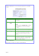
Step 3: Click the Add button to create the rule for LAN user’s bandwidth control. Parameters Rule Name Description You can set a name for the bandwidth control rule. Committed Rate (kbit) Minimum bandwidth rate of throughput. Ceiling Rate (kbit) Capped bandwidth rate of throughput. Rule Type IP/MAC Address Step 4: NOTE: The sum of the Committed Rate of all the rules should not exceed the total rate available.
Perform Remote Management (Available in Wireless Routing Client and Gateway modes) You can use the access point web-based interface from the Internet to manage your network remotely. Setup Remote Management Step 1: Select Remote Management from the CONFIGURATION command menu. Step 2: To disable Remote Management, set Remote Http Port to 0 To enable Remote Management, set Remote Http Port to an unused port number. It is recommended that you avoid using port number 80 as it is blocked by some ISPs.
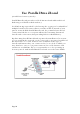
Use Parallel Broadband (Available in Gateway mode) Parallel Broadband provides scalable Internet bandwidth with Load Balancing and Fail-Over Redundancy. Load Balancing is provided by balancing the aggregate bandwidth of multiple broadband connections across the traffic demands of your private network. With Parallel Broadband, if a particular broadband connection fails, the access point will use the remaining functional broadband connections, thus providing Fail-Over Redundancy.
Enable Parallel Broadband Begin by verifying that every access point in the network is properly configured to connect to its individual broadband Internet account. Secondly ensure that either: • each access point is connected to an Ethernet port in the network OR • the access points are wired to each other. Then all the access points has to have the DHCP server, followed by the Parallel Broadband feature, enabled through the web-based configuration.
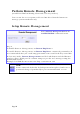
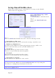
Setup Email Notification This feature notifies you by email if there is a change in the WAN IP address that was supplied to you. Step 1: Select WAN PPPoE Setup or WAN PPTP Setup from the CONFIGURATION command menu. Step 2: Click on the Email Notification button. Step 3: Select to Enable Email Notification and enter the following details: • Email address of Receiver: Email address of the receiver to whom the message would be sent.
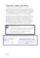
Using Static Address Translation (Available in Wireless Routing Client and Gateway modes) If you use a notebook for work in the office, you most probably bring it home to connect to the Internet as well. Since it is most likely that your office network and home network broadband-sharing network subnets are configured differently, you would have the hassle of reconfiguring your TCP/IP settings every time you use the notebook in a different place. Static Address Translation allows you to bypass this hassle.
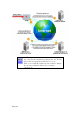
Use DNS Redirection (Available in Wireless Routing Client and Gateway modes) When you enter a URL into your Internet browser, it requests for a nameto-IP address translation from the Domain Name System (DNS) servers to locate the web server hosting the desired website. The DNS server searches its local cache for the answer, and if found, returns this cached IP address. Otherwise, it contacts other DNS servers until the query is answered.
NOTE An entry for the DNS Server field in the PC TCP/IP Properties is required for Internet access. If the exact DNS IP address is unavailable, simple key in any valid IP address, for example: 10.10.10.
Enable or Disable DNS Redirection Step 1: Select DNS Redirection from the Home User Features command menu. Step 2: Select to Enable or Disable DNS Redirection. Step 3: Click the Apply button.
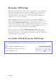
Dynamic DNS Setup With Dynamic IP Internet connection, keeping track of your public IP address for Internet communication is complicated as it is changed regularly by the ISP. If you are doing some web hosting on your computer, Internet users will have to keep up with the changing IP address to access your computer. When you sign up for an account with a Dynamic Domain Name Service (DDNS) provider, it will register your permanent domain name, for example: MyName.Domain.
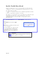
To manage Dynamic DNS List Step 1: Select Dynamic DNS Setup from the Home User Features command menu. Step 2: If you have created a list earlier, click on the Refresh button to update the list. Step 3: To add a new Dynamic DNS, click on the Add button. The Choice DDNS Provider page appears. There are two default providers that you can use. The parameters are explained below: • Choice: Indicates your preferred DDNS provider. • Provider Name: Name of your preferred DDNS provider.
2 DDNS providers are predefined for you. You need to be connected to the Internet to register your DDNS account. Select 2MyDNS – Dynamic DNS Service Provider as DDNS Service Provider: Step 1: Under the Choice column in the Choice DDNS Provider list, check the radio button next to the 2MyDNS – DNS Service Provider entry. Click on the Next button. Step 2: Enter your Domain Name. Step 3: The Auto Detect checkbox is selected by default. The WAN IP field is empty by default.
Step 5: Optional In the Mail Exchanger field, enter the Static WAN IP address of the mail server configured to handle email for your domain. Select Backup Mail Exchanger to enable this service. Step 6: Click on the Add button. The new domain is added to the Dynamic DNS list table. It will appear as a hyperlink that you can click to go back to the Dynamic DNS Edit page. Step 7: From the Dynamic DNS Edit page you can update or reset the parameters, or delete the domain name.
Select DtDNS as DDNS Service Provider: Step 1: Under the Choice column in the Choice DDNS Provider list, check the radio button next to the DtDNS entry. Click on the Next button. Step 2: Enter your Domain Name. Step 3: The Auto Detect checkbox is selected by default. The WAN IP field is empty by default. These default settings should be used if dynamic WAN IP connection is used.
Use the Wireless Extended Features Setup WDS2 WDS2 (Wireless Distributed System 2) links up access points to create a wider network in which mobile users can roam while still staying connected to available network resources. The wireless client and root access point has to be set up with the same channel frequency. This allows them to connect even when the link is lost, as the channel frequency setting is preserved.
Follow these steps to change the setup the root access point. Setup access point 1: Click on WLAN Setup from the CONFIGURATION menu. You will see the sub-menus expanded under WLAN Setup. Click on Basic. Ensure that The Current Mode is set to Access Point. To change The Current Mode, please refer to: Common Configuration – WLAN Setup - To Configure the Basic Setup of the Wireless Mode. Select Act as RootAP. Select the Channel common to both access point 1 and access point 2.
Follow these settings to setup access point 2. Setup access point 2: Click on WLAN Setup from the CONFIGURATION menu. You will see the sub-menus expanded under WLAN Setup. Click on Basic. Select the Channel common to both access point 1 and access point 2.
Configure WDS2 link: Click on WLAN Setup from the CONFIGURATION menu. You will see the sub-menus expanded under WLAN Setup. Click on Advanced. Under Extended Features, click on the WDS2 Settings button. Set WDS2 Link Status to Enable. Options for configuring WDS2 link: • By Remote AP MAC – Enter the Remote AP MAC OR • By Remote AP SSID – Uncheck the Remote AP MAC checkbox and enter the Remote AP SSID. Click Apply..
Set Virtual AP (Multiple SSID) Virtual AP implements mSSID (Multi-SSID) whereby a single wireless card can be setup with up to 16 virtual AP connections with different SSIDs or BSSID (Basic Service Set Identifier) and security modes. Virtual AP delivers multiple services by VLAN segmentation: making the network think there are many SSIDs available and channeling each connection through different VLANs to the respective virtual network segments on the Ethernet network.
Follow these steps to setup Virtual AP. Virtual AP 1 Click on WLAN Setup from the CONFIGURATION menu. Select Virtual AP. 2 Virtual AP List page displays. • Click Apply to register changes. • Click Clear to clear Virtual AP List. • Click Back to return to WLAN Basic Setup page. • Select the Delete option beside any Virtual APs you wish to delete. Click Add to goto add Virtual AP page. 3 1. Enter ESSID name. 2. Settings: • VLAN ID • Closed System • RootAP 3. Select Security Mode 4.
Set Preferred APs (Available in Client Mode) When there is more than one AP with the same SSID, the Preferred APs function allows you define the MAC address of the APs in order of preference. The MAC address at the top of the Preferred APs list has the highest connection preference, and the MAC address at the bottom has the lowest connection preference. Follow these steps to specify your preferred APs. Preferred APs 1 1. Click on WLAN Setup from the CONFIGURATION menu. 2. Select Preferred APs. 2 1.
Get Long Distance Parameters The access point can calculate and display suggested values for certain parameters to use to ensure that efficient wireless communication between physically distant access points. Select Advanced from WLAN Setup under Configuration. Click on the Long Distance Parameters button under the Extended Features section. Select to Enable the Outdoor function.
The access point can automatically calculate the values of the parameters to input based on the distance between your access point and the other wireless device. Enter the distance in meters and click on the Show Reference Data button. You can enter the parameters based on the recommended values in the popup window, click on the Apply button to update the changes.
Set Wireless Multimedia Wireless Multimedia (WMM) is a QoS (Quality of Service) standard in IEEE802.11E that we have adopted to improve and support the user experience for multimedia, video, and voice applications by prioritizing data traffic. QoS can be realized through 4 different Access Categories (AC). Each AC type consists of an independent transmit queue, and a channel access function with its own parameters.
Follow these steps to change the setup Wireless Multimedia on your access point. Step 1: 1. Click on WLAN Setup from the CONFIGURATION menu. 2. Select Advanced. Step 2: Click on the WMM Settings button. Step 3: Select to Enable Wireless Multimedia (WMM) Enter the desired WMM parameters. Using the default parameters is recommended. Click Apply to apply the WMM settings, click Default to reset all parameters to default, or click Back to discard any changes and return to WLAN Basic Setup page.
AIFs (Arbitrary Inter-Frame Space) WMM Parameters (for advanced users) Arbitrary Inter-Frame Space is the minimum wait time interval between the wireless medium becoming idle and the start of transmission of a frame over the network. Cwmin (Contention Window Minimum) Contention Window Minimum is the minimum random wait time drawn from this interval or window for the backoff mechanism on the network.
Setup Point-to-Point & Point-toMultiPoint Connection You can implement Point-to-Point connection by simply setting one access point as RootAP in Access Point mode and setting the other access points to Transparent Client mode. You can set a root access point and a transparent client to allow pointto-point communication between different buildings and enable you to bridge wireless clients that are kilometres apart while unifying the networks.
RootAP Step 2: Select Act as RootAP, click on the Apply button and reboot your device to let your changes take effect.
Follow these steps to setup Transparent Client/s. Transparent Client Step 1: Click on WLAN Setup from the CONFIGURATION menu. You will see the sub-menus expanded under WLAN Setup. Click on Basic. Ensure that The Current Mode is set to Transparent Client. To change The Current Mode, please refer to: Common Configuration – WLAN Setup - To Configure the Basic Setup of the Wireless Mode.
Transparent Client Step 2: Select the Remote AP MAC checkbox. Enter the Remote AP MAC. Note: When using Remote AP MAC, the ESSID name must also match the AP’s ESSID name, especially when Closed System is enabled on the AP. Repeat Transparent Client step to add more points to the Point-toMultiPoint connection.
Setup Repeater A Repeater AP can connect to an AP only if the option Act as RootAP is set or checked in the AP setup. Example: Network diagram with 2 repeater hops. NOTE As bandwidth degrades with every repeater hop it is recommended that a limit of 4 hops is not exceeded.
NOTE DO NOT physically connect your PC to the server via Ethernet cable in addition to the wireless connection, as doing so will create a loop that is not prevented by wireless loop preventing feature.
Follow these settings to setup the root AP. Root AP Settings: Click on WLAN Setup from the CONFIGURATION menu. You will see the sub-menus expanded under WLAN Setup. Click on Basic. Ensure that The Current Mode is set to Access Point. To change The Current Mode, please refer to: Common Configuration – WLAN Setup - To Configure the Basic Setup of the Wireless Mode. Select Act as RootAP. Click Apply.
Follow these settings to setup the repeater. Repeater Settings: Click on WLAN Setup from the CONFIGURATION menu. You will see the sub-menus expanded under WLAN Setup. Click on Basic. Ensure that The Current Mode is set to Repeater. To change The Current Mode, please refer to: Common Configuration – WLAN Setup - To Configure the Basic Setup of the Wireless Mode.
Options for defining the root AP: • Accept the default Remote ESSID (root AP’s SSID) OR • Enter the Remote ESSID. OR • Check and enter the Remote BSSID (root AP’s MAC address) Click Apply..
Secure your Wireless LAN Step 1: Select Security from WLAN Setup under the CONFIGURATION menu. Step 2: Make a selection from the Security Mode drop-down list. The Security Mode is set to NONE by default. Click on the Apply button. NOTE All nodes in your network must share the same wireless settings in order to communicate.
Setup WEP At the WEP Setup page, Step 1: Select the Transmission Key from the pull down menu: • Key 1 • Key 2 • Key 3 • Key 4 Step 2: Specify the key entry type, by selecting either: • Use Hexadecimal: • Use ASCII The access point lets you define up to four different transmission keys. It defines a set of shared keys for network security. You must enter at least one WEP key to enable security using a shared key.
Setup WPA-Personal (Available in Access Point, Repeater and Gateway Modes) Follow these steps if you have activated the WPA-Personal, WPA2Personal or WPA-Personal-AUTO security modes.
Step 3: For WPA-Personal Set the Cipher Type to TKIP. WPA replaces WEP with a strong encryption technology called Temporal Key Integrity Protocol (TKIP) with Message Integrity Check (MIC). For WPA2-Personal Set the Cipher Type to AES. Advanced Encryption Standard (AES) is a stronger symmetric 128-bit block data encryption technique. AES is a requirement of WPA2 under the IEEE 802.11i standard.
Setup 802.1x/RADIUS for Access Point (Available in Access Point, Repeater and Gateway Modes) At the IEEE 802.1x AP Setup page, Step 1: Key in the IP address of the Primary RADIUS Server in your WLAN. You can optionally add in the IP address of a Secondary RADIUS Server, if any. The RADIUS authentication server MUST be in the same subnet as the access point. Step 2: By default, the value for Authentication Port number is 1812. You can leave this value as it is.
Step 6: Select the length of each encryption key: • 64- bit 10 hexadecimal or 5 ASCII Text • 128-bit 26 hexadecimal or 13 ASCII Text Step 7: Click the Apply button and reboot your system, after which your settings will become effective.
Setup 802.1x/RADIUS for Client (Available in Client, Transparent Client, Wireless Routing Client and Wireless Adapter Modes) At the IEEE 802.1x Client Setup page, Step 1: Select whether to use EAP-TTLS or EAP-PEAP 802.1x EAP Type. Step 2: Both EAP-TTLS (Extensible Authentication Protocol - Tunneled Transport Layer Security) and EAP-PEAP (Protected Extensible Authentication Protocol) support identity hiding. In the WLAN, the access point generates an identity request.
If using EAP-PEAP 802.1x EAP Type: • • Enter the User Name. Enter the Password. Step 3: Click the Apply button and reboot your system, after which your settings will become effective.
Setup WPA Enterprise for Access Point (Available in Access Point, Repeater and Gateway Modes) Follow these steps if you have selected the WPA1-Enterprise, WPA2Enterprise, or WPA-Enterprise-AUTO security modes. At the WPA1/2-Enterprise AP Setup page, Step 1: Key in the IP address of the Primary RADIUS Server in your WLAN. You can optionally add in the IP address of a Secondary RADIUS Server, if any. The RADIUS authentication server MUST be in the same subnet as the access point.
Setup WPA Enterprise for Client (Available in Client, Transparent Client, Wireless Routing Client and Wireless Adapter Modes) Follow these steps if you have selected the WPA1-Enterprise, WPA2Enterprise, or WPA-Enterprise-AUTO security modes.
Step 1: Select whether to use EAP-TTLS or EAP-PEAP WPA EAP Type. Step 2: Both EAP-TTLS (Extensible Authentication Protocol - Tunneled Transport Layer Security) and EAP-PEAP (Protected Extensible Authentication Protocol) support identity hiding. In the WLAN, the access point generates an identity request. To preserve anonymity, the client responds with only enough information to allow the RADIUS server to process the request. If using EAP-TTLS WPA EAP Type: • • • • Enter the User Name.
If using EAP-PEAP WPA EAP Type: • • • • Enter the User Name. Enter the Anonymous Identity attribute for EAP-TTLS. Enter the Password. Enter the Cipher Type. For WPA-Enterprise Set the Cipher Type to TKIP. WPA replaces WEP with a strong encryption technology called Temporal Key Integrity Protocol (TKIP) with Message Integrity Check (MIC). For WPA2- Enterprise Set the Cipher Type to AES. Advanced Encryption Standard (AES) is a symmetric 128-bit block data encryption technique.
Configure the Security Features Use Packet Filtering Packet filtering selectively allows /disallows applications from Internet connection. Configure Packet Filtering (Available in Wireless Routing Client and Gateway modes) Step 1: Select Packet Filtering from the Security Configuration command menu. Step 2: Select the Packet Filter Type by clicking on the Change button. Step 3: Select from three choices: Disabled, Sent, Discarded, and then click on the Apply button.
A Range of IP addresses In this case, you will have to define (From) which IP address (To) which IP address, your range extends. A Single IP address Here, you need only specify the source IP address in the (From) field. Any IP address You may here, leave both, the (From) as well as the (To) fields, blank. Here, the rule will apply to all IP addresses. 4c).
4e). At the Time of the Day drop down list, you may also choose to apply the rule to: A Range of time In which case, you have to specify the time in the format HH:MM, where HH may take any value from 00 to 23 and MM, any value from 00 to 59. Any time Here, you may leave both (From) and (To) fields blank. Step 5: Click on the Apply button to make the new rule effective. The Filtering Configuration table will then be updated.
Use URL Filtering URL Filtering allows you to block objectionable websites from your LAN users. Configure URL Filtering (Available in Wireless Routing Client and Gateway modes) Step 1: Select URL Filtering from the Security Configuration command menu. Step 2: To select the URL Filter Type, click the Change button. Step 3: Select to Block or Allow, and then click on the Apply button. The default is Disabled, which allows all websites to be accessed. Then click the Add button.
Configure the Firewall Configure SPI Firewall (Available in Wireless Routing Client and Gateway modes) Stateful Packet Inspection (SPI) thwarts common hacker attacks like IP Spoofing, Port Scanning, Ping of Death, and SynFlood by comparing certain key parts of the packet to a database of trusted information before allowing it through. NOTE Firewall security rules should be planned carefully as incorrect configuration may cause improper network function.
You may add more firewall rules for specific security purposes. Click on the Add radio button at the screen shown above, followed by the Edit button. Rule : Enter a unique name to identify this firewall rule. Name Disposition : This parameter determines whether the packets obeying the rule Policy should be accepted or denied by the firewall. Choose between Accept and Deny. Protocols : Users are allowed to select the type of data packet from: TCP, UDP, ICMP, IGMP or ALL.
Destination unreachabl e Source quench Redirect Time exceeded Parameter Problem Timestamp Request Information Request Information Reply IGMP Types Source IP Informs the host that a datagram cannot be delivered. Informs the host to lower the rate at which it sends datagrams because of congestion. Informs the host of a preferred route. Indicates that the Time-toLive (TTL) of an IP datagram has expired. Informs that host that there is a problem in one the ICMP parameter.
Destinatio n Port : This parameter determines the application from the specified destination port. Users can either set a single port number or a range of port numbers. Check Options : This parameter refers to the options in the packet header.
Use the Firewall Log The Firewall Log captures and stores network traffic information such as the type of data traffic, the time, the source and destination address / port, as well as the action taken by the firewall. View Firewall Logs (Available in Wireless Routing Client and Gateway modes) Step 1: Select Firewall Log from the SECURITY CONFIGURATION command menu. Step 2: Click on the Refresh button to see the information captured in the log: Time at which the packet was detected by the firewall.
Administer the System Use the System Tools Use the Ping Utility (Available in Wireless Routing Client and Gateway modes.) You can check whether the access point can communicate (ping) with another network host with the Ping Utility. Step 1: Select Ping Utility under the SYSTEM TOOLS command menu. Step 2: Enter the IP address of the target host to ping. Click the Start button. The Ping messages are displayed.
Use Syslog Syslog forwards system log messages in a network to a machine running a Syslog listening application. It is used to help in managing the computer system and increase security on the network. Freeware supporting Syslog is widely available for download from the Internet. This section shows how to: • Setup Syslog. • View logged information. The System Log Setup page allows the user to: • Enable or Disable system logging.
Follow these steps to setup Syslog: Step 1: Click on Syslog from the SYSTEM TOOLS menu. Step 2: Select to Enable Syslog. Enter the Logging IP or Domain Name Enter the Logging Port Click Apply to make the changes.
Follow these sample steps to view logged information: Step 1: Search for a Syslog listening application. Step 2: Select a Syslog listening application. Step 3: Download Syslog listening application. Step 4: Install Syslog listening application. Step 5: View logged information on Syslog listening application.
Setup System Clock Step 1: Select System Clock Setup from the SYSTEM TOOLS menu. Step 2: Select the appropriate time zone from the Select to Change the Time Zone for the Router Location drop-down list. Step 3: Enable the Auto Time Setting (SNTP) radio button. SNTP stands for Simple Network Time Protocol and is used to synchronise computer clocks. Step 4: Fill in the Time Servers field and click on the Apply button to effect the changes.
Upgrade the Firmware with uConfig You can check the types and version of your firmware by clicking on About System from the HELP menu. To begin with, ensure that you have the updated firmware available. Step 1: Select Firmware Upgrade from the SYSTEM TOOLS menu. Step 2: Click on the Browse button to locate the file. Step 3: Click on the Upgrade button. Follow the instructions given during the upgrading process.
Step 4: You need to reboot the system after the firmware upgrade. NOTE The firmware upgrade process must NOT be interrupted; otherwise the device might become unusable.
Upgrade the Firmware with Command Line Interface You can check the types and version of your firmware by clicking on About System from the HELP menu in UConfig. Follow these steps to upgrade firmware from Command Line Interface (CLI). Step 1: Ensure that you have the updated firmware available. Step 2: On the PC connected to the AP, run a TFTP server and setup to point to the same firmware image filename.
Step 3: In the Command Line Interface, enter the command with the IP address of the AP and the filename of the firmware image as the parameters: Set upgrade Step 4: These screens display when upgrade is done. Sample Screenshot NOTE The firmware upgrade process must NOT be interrupted; otherwise the device might become unusable.
Perform Firmware Recovery If the system fails to launch properly, the access point will automatically switch to loader mode and the diagnostic LED will remain lighted. The firmware should then be reloaded. Access Point State Corrupted firmware – access point automatically switches to loader mode Recovery in progress Successful recovery Diagnostic LED ( ) State Blinks very fast ON Blinks very slowly Before starting, check the status of the diagnostic LED to confirm if firmware failure has occurred.
Step 5: From the Start menu, click Run and type cmd. When the command prompt window appears, type in the following command: X:\recovery\TFTP -i 192.168.168.1 PUT image_name.IMG, where X refers to your CD drive and image_name.IMG refers to the firmware filename found in the Recovery folder of the Product CD. Step 6: If you have downloaded a newer firmware and have saved it in your local hard disk as: C:\accesspoint\accesspointxxx.IMG, then replace the command with this new path and firmware name.
Backup or Reset the Settings You may choose to save the current configuration profile, create a backup of it on your hard disk, restore an earlier saved profile, or to reset the access point back to its default settings. Reset your settings Step 1: Select Backup or Reset Settings from the SYSTEM TOOLS menu. Step 2: To discard configurations made and restore the access point to its initial factory settings, click on the Reset button.
Backup your Settings Step 1: Select Backup or Reset Settings from the SYSTEM TOOLS menu. Step 2: To back up the current settings of your access point onto your hard disk drive, click on the Backup button. Step 3: Save your configuration file to your local disk.
Restore your Settings Step 1: Select Backup or Reset Settings from the SYSTEM TOOLS menu. Step 2: To restore previously saved settings, click on the Browse… button and select the folder where you saved your configuration file. Click on the Restore button and the system will prompt you to reboot your device.
Reboot the System Most of the changes you make to the system settings require a system reboot before the new parameters can take effect. Step 1: Select Reboot System from the SYSTEM TOOLS menu. Step 2: Click on the Reboot button. Step 3: Wait for the system to reboot and the login page will be displayed.
Change the Password It is recommended that the login password is changed from the factory default password. Step 1: Select Change Password from the SYSTEM TOOLS menu. Step 2: Key in the Current Password. The password is case-sensitive and defaulted to password Enter the New Password field and then Confirm Password. Step 3: Click on the Apply button to update the changes.
To Logout Step 1: Select Logout from the SYSTEM TOOLS menu. Step 2: Click the LOGIN! button to access the access point configuration interface again.
Use the HELP menu View About System System Information displays system configuration information that may be required by support technicians for troubleshooting. Select About System from the HELP menu. The System Information page displays information about the access point configuration settings.
Get Technical Support This page displays the contact information of technical support centres around the world. If further information unavailable in the manual or data sheet is required, please contact a Technical Support Centre by mail, email, fax or telephone. Click on Get Technical Support from the HELP menu.
Appendix: Use the Command Line Interface Get Operation List SYNTAX Get tasks Get sysinfo Get aplist Get athstats Get brinfo Get brmacshow Get bssinfo. Get channel Get chanlist Get ieee80211stats Get routeshow Get stalist Get linkinfo Get macstats Get opmode Get wmode DESCRIPTION Display all active process/tasks. Display system information. Display list of access points discovered. Display wireless driver information. Display bridge and interfaces information. Display bridge learned MAC address list.
Wireless Mode SYNTAX Set wirelessmode Set autochannelselect Enable/disable Set radio_off_eth_down enable/disable DESCRIPTION Supported strings are: auto, 11a, 11b, 11g, pureg, superg, supera Enable or disable smart channel select during power up. Enable or disable auto turn off radio when Ethernet port connection link is lost. WEP Key Must first set a key entry type, and then proceed to set the key index, size, and value.
{CTRY_ITALY, "IT" }, {CTRY_JAPAN, "JP" }, {CTRY_JAPAN1, "J1" }, {CTRY_JAPAN2, "J2" }, {CTRY_JAPAN3, "J3" }, {CTRY_JAPAN4, "J4" }, {CTRY_JAPAN5, "J5" }, {CTRY_JAPAN6, "J6" }, {CTRY_JORDAN, "JO" }, {CTRY_KAZAKHSTAN, "KZ" }, {CTRY_KOREA_NORTH, "KP" }, {CTRY_KOREA_ROC, "KR" }, {CTRY_KOREA_ROC2, "K2" }, {CTRY_KOREA_ROC3, "K3" }, {CTRY_KUWAIT, "KW" }, {CTRY_LATVIA, "LV" }, {CTRY_LEBANON, "LB" }, {CTRY_LIECHTENSTEIN, "LI" }, {CTRY_LITHUANIA, "LT" }, {CTRY_LUXEMBOURG, "LU" }, {CTRY_MACAU, "MO" }, {CTRY_MACEDONIA, "
Channel SYNTAX Set channel DESCRIPTION (Value in decimal) SSID SYNTAX Set ssid DESCRIPTION (Not More than 32 characters) Closed System SYNTAX Set hidessid enable/disable DESCRIPTION Enable or disable broadcasting of SSID. Per Node SYNTAX Set apbridge enable/disable DESCRIPTION Enable or disable isolation of wireless client.
Custom Configuration Update SYNTAX DESCRIPTION Cfgfile The cfgfile command is used for managing simple configuration changes to multiple access points. It is useful for when the user has many access points to configure and the configuration is mostly the same. For example if user needs to configure ten access points, and just change the IP address configuration: 1.
Appendix: Virtual AP (Multi-SSID) FAQ Q1) What is mSSID? Multi-SSID (mSSID) as the name suggest, allows an access point (AP) with a single radio card to support more than one SSID. Q2) What can you do with mSSID connection? The application of mSSID is to provide better security with multiple network path connections from a single AP, to multiple VLAN network segments of the switch on the local area network. A network setup application is illustrated below. E.g.
Q3) Can I update my access point to this mSSID firmware? Yes. You can retain your access point configuration when you update to the mSSID firmware if the current firmware running is v1.3x and above. If AP is running the following configuration setup, updating to the mSSID firmware will affect the configuration. If AP is running as PtP (Point-To-Point) or PtMP (Point-To-MultiPoint) mode.
Q6) I have Pseudo VLAN for Per Group enabled. Will updating to mSSID firmware still support wireless clients with MAC addresses listed in Per Group? The mSSID firmware replaces Pseudo VLAN and integrates it into VAP (Virtual AP) and MAC Filtering. Thus, Pseudo VLAN with its VLAN ID and MAC listing will be lost after updating to mSSID firmware. Refer to the user manual on how to create new VAP with VLAN ID and MAC Filtering.
Q8) I have 2 of the access point units installed at a site about 2km from each other running PtP modes. Should I update to mSSID firmware? Can I do it from one location to update the firmware like I do with the current single SSID firmware? The setup for PtP and PtMP for mSSID firmware is different the current sSSID firmware. After mSSID firmware starts up, the link between the 2 APs will be lost. The recommended method is to setup 2 similar model units in the office.
Appendix: View the Technical Specifications • • • • • • • FCC Part 15 SubPart B and SubPart C (for wireless module) EN 300 328-2 EMC CE EN 301 489 (EN300 826) EN 55022 (CISPR 22)/EN 55024 Class B EN 61000-3-2 EN61000-3-3 CE EN 60950 Standards IEEE802.11b: • 11Mbps, 5.5Mbps, 2Mbps, 1Mbps IEEE802.11g: • 54Mbps, 48Mbps, 36Mbps, 24Mbps, 18Mbps, 12Mbps, 9Mbps, 6Mbps, automatically fallback to 5.
Configuration Backup & Restore Yes Firmware Upgrade Yes Power Requirements Using Power Adapter: Using PoE: 24VDC 15-48VDC Operating Temp: -20ºC to +70ºC Storage Temp: -30ºC to +80ºC Operating Humidity: Physical Dimensions Page 182 10% to 80% RH Humidity (RH – Relative Humidity) 91.
© Copyright 2007 Compex Systems Pte Ltd All Rights Reserved This document contains information, which is protected by copyright. Reproduction, adaptation or translation without prior permission is prohibited, except as allowed under the copyright laws. Trademark Information Compex® is a registered trademark of Compex, Inc. Microsoft Windows and the Windows logo are the trademarks of Microsoft Corp. NetWare is the registered trademark of Novell Inc.
FCC Compliance Statement: This device complies with Part 15 of the FCC Rules. Operation is subject to the following two conditions: This device may not cause harmful interference, and This device must accept any interference received, including interference that may cause undesired operation. Products that contain a radio transmitter are labelled with FCC ID and may also carry the FCC logo. Caution: Exposure to Radio Frequency Radiation.
Technical Support Information The warranty information and registration form are found in the Quick Install Guide. For technical support, you may contact Compex or its subsidiaries. For your convenience, you may also seek technical assistance from the local distributor, or from the authorized dealer/reseller that you have purchased this product from. For technical support by email, write to support@compex.com.sg.
warning Class B: This equipment has been tested and found to comply with the limits for a Class B digital device, pursuant to part 15 of the FCC Rules. These limits are designed to provide reasonable protection against harmful interference in a residential installation. This equipment generates, uses and can radiate radio frequency energy and, if not installed and used in accordance with the instructions, may cause harmful interference to radio communications.