CompatiView 5.4 Reference Guide Compatible Systems Corporation 4730 Walnut Street Suite 102 Boulder, Colorado 80301 303-444-9532 800-356-0283 http://www.compatible.
CompatiView Reference Guide, Version 5.4 Copyright © 1999, Compatible Systems Corporation All rights reserved. CompatiView, RISC Router, MicroRouter, IntraPort and IntraGuard are trademarks of Compatible Systems Corporation. Other trademarks are the property of their respective holders.
Table of Contents TENTS iii Chapter 1 - Installation and Overview 1 COMPATIVIEW QUICKSTART . . . . . . . . . . . . . . . . . . . . . . . . . . . . . . . . . . . . . . . . 1 ABOUT THIS MANUAL . . . . . . . . . . . . . . . . . . . . . . . . . . . . . . . . . . . . . . . . . . . . . . 2 COMPATIVIEW INSTALLATION NOTES . . . . . . . . . . . . . . . . . . . . . . . . . . . . . . . . . 2 COMPATIVIEW’S MENUS AND MAIN WINDOWS . . . . . . . . . . . . . . . . . . . . . . . . . 3 MOVING AND CUSTOMIZING THE WINDOWS .
iv Table of Contents Chapter 6 - VPN Ports and LAN-to-LAN Tunnels 97 ADD VPN PORT DIALOG BOX . . . . . . . . . . . . . . . . . . . . . . . . . . . . . . . . . . . . . . 97 TUNNEL PARTNER: VPN CONFIGURATION DIALOG BOX . . . . . . . . . . . . . . . . . . 98 IKE KEY MANAGEMENT . . . . . . . . . . . . . . . . . . . . . . . . . . . . . . . . . . . . . . . . . . 99 MANUAL KEY MANAGEMENT . . . . . . . . . . . . . . . . . . . . . . . . . . . . . . . . . . . . . 102 INTEROPERABILITY SETTINGS DIALOG BOX . . . . . .
Table of Contents v Chapter 11 - TCP/IP Filtering 183 MAIN TCP/IP FILTERING DIALOG BOX . . . . . . . . . . . . . . . . . . . . . . . . . . . . . . 183 TCP/IP FILTER EDITOR WINDOW . . . . . . . . . . . . . . . . . . . . . . . . . . . . . . . . . . . 184 TCP/IP ROUTE FILTER RULES . . . . . . . . . . . . . . . . . . . . . . . . . . . . . . . . . . . . . 185 TCP/IP PACKET FILTER RULES . . . . . . . . . . . . . . . . . . . . . . . . . . . . . . . . . . . . 188 TCP/IP PACKET FILTERING: ETHERNET DIALOG BOX . . .
vi Table of Contents SECURID CONFIGURATION DIALOG BOX . . . . . . . . . . . . . . . . . . . . . . . . . . . . . 239 NAT CONFIGURATION DIALOG BOX . . . . . . . . . . . . . . . . . . . . . . . . . . . . . . . . 241 NAT RANGE DIALOG BOX . . . . . . . . . . . . . . . . . . . . . . . . . . . . . . . . . . . . . . . . 244 NAT MAPPING DIALOG BOX . . . . . . . . . . . . . . . . . . . . . . . . . . . . . . . . . . . . . . 245 LOGGING CONFIGURATION DIALOG BOX . . . . . . . . . . . . . . . . . . . . . . . . . . . .
Chapter 1 - Installation and Overview 1 Chapter 1 - Installation and Overview CompatiView Quickstart • Follow the instructions in the Installation Guide for your internetworking device to connect it to your network. • Install CompatiView by running the install program included on the CD-ROM which was included with your Compatible Systems device. • Run CompatiView. • Select a network transport protocol using the Database menu’s Options dialog box.
2 Chapter 1 - Installation and Overview About this Manual This manual documents CompatiView v5.3, which can be used to configure and manage all Compatible Systems products except the MicroRouter 900i and 1000R and the RISC Router 3000E. CompatiView v4.8x may be used to configure those devices. CompatiView v4.8x is available in the Network Management\CompatiView\Windows directory on the CD-ROM that was included with your shipping package and in the Software Downloads section of our Web site (http://www.
Chapter 1 - Installation and Overview 3 default of Ethernet A/0 on all devices). After setting the device’s IP address, be sure to change the workstation’s configuration back to its original settings. To use IPX, which will allow you to contact the device without setting any parameters over the device’s Console port, you can either set the appropriate radio button in the Database menu’s Options dialog box or click on the IP/IPX box at the bottom of the main CompatiView screen.
4 Chapter 1 - Installation and Overview • The Help menu, which provides standard help functions. v Note: Some of the menu items will be grayed out unless you are currently logged into a device. Where applicable, menu selections are put into effect for the current device. This is the device which is currently highlighted in the Device View and is shown in the title of the CompatiView screen.
Chapter 1 - Installation and Overview 5 If the device is a multislot product such as a VSR or IntraPort Enterprise, both the slot number and the interface number are shown, separated by a colon (e.g., Ethernet 0:0 indicates Slot 0, Ethernet 0, while Ethernet 1:0 indicates Slot 1, Ethernet 0). Administrative information will also be included if it has been set using the Item Properties option under the Database Menu. The list of configuration items associated with each device is an edit area.
6 Chapter 1 - Installation and Overview The File Menu The File menu provides options which allow you to create and manage configurations in CompatiView’s Device View. New Config This option loads default parameters for a particular type of device in the Device View. You will first be asked to select a device type from a list. This option may be useful to preconfigure a device or to use as a base configuration for multiple devices.
Chapter 1 - Installation and Overview 7 Download Config to Device Dialog Box Save / Restart Options The settings in this dialog box are specific for this device. For global Save/Restart settings use the Database menu, select options, and choose the Save/Restart tab. To change the Save/Restart mode for a particular device, modify the “Device Properties” for that device. • Save config and restart device.
8 Chapter 1 - Installation and Overview current operations without restarting the device. This is the equivalent of issuing the apply command and then the write command in the command line. While the download is taking place, arrows will move in a circular motion around the device icon in the Device View. To display the amount of time left for the download, click on the + sign next to the device icon. M Caution: Turning off a device in the middle of a download may cause it to lose its operating software.
Chapter 1 - Installation and Overview 9 Delete opens a confirmation prompt to delete the path. You must have a firewall path selected to enable the Delete option. View This menu item brings up the Local Config View tab in the Output Window, which displays the configuration text file for the current device. Print This menu item prints the configuration text file for the current device. Recent File This menu item holds a list of files that have recently been saved.
10 Chapter 1 - Installation and Overview Options This menu item brings up a dialog box which lets you set a variety of options having to do with CompatiView’s operation. Database Options Dialog Box General Tab • IPX Transport - IP Transport. This set of radio buttons determines whether CompatiView for Windows will use IPX or IP as a transport. • Load IPX upon startup. CompatiView runs IPX behind the scenes to generate IPX tables.
Chapter 1 - Installation and Overview 11 be loaded to the file on disk. If left unchecked, you will be prompted each time the config files are changed and not loaded to disk. • Hide Data in Secure fields. This checkbox will not show passwords in display dialogs or edit boxes, or the text configuration of the current device in Local Config View at the bottom of the screen. If this box is not checked, passwords will be displayed in the clear. • Cascade new windows as they are opened.
12 Chapter 1 - Installation and Overview • Save config, but don’t restart device. This parameter will save an edited configuration without restarting the device. The changes will not be applied until the device is restarted. This is the equivalent of the command line’s write command. • Don’t save config, but use new config immediately. This parameter will apply an edited (but not saved) configuration to the device’s current operations. If a restart occurs, changes will be lost.
Chapter 1 - Installation and Overview 13 The Control menu lets you update the software contained in the Flash ROM of a device. Download Software When new features are added to the operating software for a particular type of device, you may wish to update a device with the new version. When you are using IPX transport protocols and select this option, a window listing all eligible devices will appear. You will first be asked to select one or more devices (which must all be of the same type).
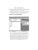
14 Chapter 1 - Installation and Overview The Output Window The CompatiView Output Window There is an Output Window at the bottom of the Device View which lets you quickly check the current status of the selected configuration parameter or review the device configuration. The tabs show different types of parameter values. In some cases, these parameters may be different than those stored in the device’s Flash ROM due to auto-configuration. The Output Window is broken up into three tabbed sections.
Chapter 1 - Installation and Overview 15 be used by Compatible Systems technical support to determine the cause of many problems. Ethernet This menu item displays ethernet port statistics and is the equivalent of the command line’s show ethernet statistics command. (See the ethernet(show) section.) WAN State This menu item displays WAN port status and connection statistics and is the equivalent of the command line’s show wan state command. (See the wan(show) section.
16 Chapter 1 - Installation and Overview IP Route Table This menu item displays the IP route table and is the equivalent of the command line’s show ip routing command. (See the ip(show) section.) IP Routing This menu item displays IP statistics and is the equivalent of the command line’s show ip statistics command. (See the ip(show) section.) IPX Route Table This menu item displays the IPX route table, and is the equivalent of the command line’s show ipx routing command. (See the ipx(show) section.
Chapter 1 - Installation and Overview 17 OSPF Neighbors This menu item displays an abbreviated list of current neighbors an their state. This is equivalent to the command line’s show ospf nbr command. (See the ospf(show) section) Buffer This menu item displays detailed information on the current status of the device’s memory allocation and is the equivalent of the command line’s show os memory command. (See the os(show) section.
18 Chapter 1 - Installation and Overview Moving and Customizing the Windows Right-clicking in the area between windows brings up a popup menu which controls the placement of the windows. • Allow Docking. This menu option, when checked, allows the window to be docked in a firm place within the main window. • Hide. This menu option will hide the selected window. Use the Window menu to view a hidden window again.
Chapter 1 - Installation and Overview 19 Customize Window View Dialog Box Toolbars This tab allows you to choose the toolbars that you want in your display window. Commands This tab allows you to create your own toolbar by placing device commands or command line buttons onto any toolbar. The Window Menu This menu allows you to toggle the database workspace (device view) and the output window. You can also choose how your windows will be displayed in the workspace.
Chapter 2 - IP Routing & Bridging 21 Chapter 2 - IP Routing & Bridging TCP/IP Routing: Ethernet Dialog Box TCP/IP Routing: Ethernet Configuration Dialog Box v Note: If you need more information about the IP protocol, see “IP 101” in the Appendices to this manual. To access this dialog box, select Ethernet/TCP/IP Routing from the Device View. > IP Routing/Bridging/Off This set of radio buttons controls how IP packets are handled for this interface.
22 Chapter 2 - IP Routing & Bridging v Note: The IP Bridging radio button will be grayed out unless bridging has been turned on globally for the device using the Main Bridging Configuration Dialog Box (under Global/Bridging) and locally on this interface using the Bridging: Ethernet Dialog Box (under Ethernet/Bridging). • > If set to IP Off, then any IP packets received on this interface are discarded.
Chapter 2 - IP Routing & Bridging 23 the address. A few networks use all zeroes in this field. If you are unsure which type your network uses, check with your network administrator. To have CompatiView calculate a default broadcast address, make sure that the Broadcast Address field is empty, position the cursor in the Subnet Mask field, then just tab through the Broadcast Address field.
24 Chapter 2 - IP Routing & Bridging • If None is selected with this pull-down menu, the router will not be able to update its routing table and will always direct traffic for addresses it does not have a route for (addresses not on one of the networks connected to its interfaces) to the “gateway/port” defined in its IP Static Route Dialog Box. It will then be the responsibility of the default router to direct the packets to the correct address.
Chapter 2 - IP Routing & Bridging 25 Directed Broadcast This checkbox sets whether the interface will forward network-prefix-directed broadcasts. This is a security feature which can help prevent your network from being used as an intermediary in certain kinds of attacks which use ICMP echo traffic (pings) or UDP echo packets with fake (i.e., “spoofed”) source addresses to inundate a victim with erroneous traffic.
26 Chapter 2 - IP Routing & Bridging TCP/IP Routing: WAN Configuration Dialog Box TCP/IP Routing: WAN Configuration Dialog Box v Note: If you need more information about the IP protocol, see “IP 101” in the Appendices to this manual. To access this dialog box, select WAN/TCP/IP Routing from the Device View. > IP Routing/Bridging/Off This set of radio buttons controls how IP packets are handled for this interface.
Chapter 2 - IP Routing & Bridging 27 v Note: The IP Bridging radio button will be grayed out unless bridging has been turned on globally for the device using the Main Bridging Configuration Dialog Box (under Global/Bridging) and locally on this interface using the Bridging: WAN Dialog Box (under WAN/Bridging). • > If set to IP Off, then any IP packets received on this interface are discarded.
28 Chapter 2 - IP Routing & Bridging what part of the IP address identifies the network segment (the “network” portion), and what part identifies individual interfaces (the “host” portion). There are three generally used “classes” of subnetted IP networks: A, B and C. Each class uses a different amount of the IP address for the network and host portions. These classes may also be further divided by correctly setting the subnet mask.
Chapter 2 - IP Routing & Bridging 29 RIP 2 is more useful in a variety of environments and allows the use of variable subnet masks on your network. It is also necessary for implementation of “classless” addressing as accomplished with CIDR (Classless Inter Domain Routing). It is recommended that RIP 2 be used on any segment where all routers can use the same IP routing protocol. If one or more routers on a segment must use RIP 1, then all other routers on that segment should also be set to use RIP 1.
30 Chapter 2 - IP Routing & Bridging • If Triggered is selected with this pull-down menu, the router will modify the standard RIP behavior for this interface to send RIP packets only when there has been an update to its routing table information, or when it has detected a change in the accessibility of the next hop router. • If Periodic is selected with this pull-down menu, the router will use the standard RIP protocol, which sends RIP packets over the link every 30 seconds.
Chapter 2 - IP Routing & Bridging 31 Options The options button brings up the WAN IP Options Dialog Box which allows you to set a Remote Node IP Address, Van Jacobson Header Compression, and other configuration information. This dialog box is discussed later in this chapter. OSPF This option button brings up the OSPF Dialog Box which allows the OSPF routing protocol to be enabled. For more information on this dialog box and other OSPF parameters, refer to Chapter 15 - OSPF.
32 Chapter 2 - IP Routing & Bridging Once you have created a VPN port, you may access the TCP/IP Routing: VPN Configuration Dialog Box by clicking TCP/IP Routing under the VPN port’s icon. A VPN port is a virtual port which handles tunneled traffic. Tunnels are virtual point-to-point connections through a public network such as the Internet. All packets sent through a VPN tunnel are IP-encapsulated packets, including AppleTalk, IPX and even IP packets.
Chapter 2 - IP Routing & Bridging • 33 If checked, then you must set an IP Address, Subnet Mask, and Broadcast Address (as described below) for this VPN port. The default is unchecked. IP Address If you wish to assign an IP address, it must be unique. Part of this address identifies the network segment the router interface is connected to, and the remainder uniquely identifies the router interface itself. This address should be entered as four decimal numbers separated by periods -- for example, 198.
34 > Chapter 2 - IP Routing & Bridging Routing Protocol Routers exchange information about the most effective path for packet transfer between various end points. There are a number of different protocols which have been defined to facilitate the exchange of this information. Routing Information Protocol (RIP) 1 is the most widely used routing protocol on IP networks. All gateways and routers that support RIP 1 periodically broadcast routing information packets.
Chapter 2 - IP Routing & Bridging 35 default router see the discussion of the IP Static Route Dialog Box later in this chapter. v Note: Some routers, in particular those designed to create very large corporate backbones, may use other routing protocols such as OSPF (Open Shortest Path First). These routers can simultaneously use RIP 1 (and in some cases RIP 2) to communicate with smaller routers, or each of the smaller routers can be set to use one of these backbone routers as their default router.
36 Chapter 2 - IP Routing & Bridging • If No Split Horizon is selected with this pull-down menu, the device will include all routes in an output packet, regardless of which interface they were acquired over, and will use a normal metric. • If Poison Reverse is selected with this pull-down menu, the device will include all routes in an output packet, but will set the metric to infinity for those routes which were acquired over this interface.
Chapter 2 - IP Routing & Bridging 37 TCP/IP Routing: Bridge Configuration Dialog Box IP Bridge Group Port 0 Port 1 Port 2 Port 3 IPX Bridge Group Multiport Router/Switch Bridge Logical Diagram v Note: If you need more information about bridging, see “Bridging 101” in the Appendices to this manual. Bridging operates on physical network addresses (such as Ethernet addresses), rather than logical addresses (such as IP addresses).
38 Chapter 2 - IP Routing & Bridging TCP/IP Routing: Bridge 0 Configuration Dialog Box v Note: If you need more information about the IP protocol, see “IP 101” in the Appendices to this manual. To access this dialog box, select Bridge 0/TCP/IP Routing from the Device View. > > IP Routing/Off These radio buttons control whether IP packets received by a member interface of the IP Bridge Group are passed on for IP routing.
Chapter 2 - IP Routing & Bridging 39 This address should be entered as four decimal numbers separated by periods -- for example 198.238.9.5 v Note: The single most common problem encountered in IP networking is the use of a duplicate IP address. You must carefully track the network numbers you have assigned to various devices in order to avoid hard-to-diagnose problems. > Network IP Subnet Mask Most IP networks use “subnetting” in order to subdivide a large network into smaller logical sub-networks.
40 Chapter 2 - IP Routing & Bridging ically broadcast routing information packets. These RIP 1 packets contain information concerning the networks that the routers and gateways can reach as well as the number of routers/gateways that a packet must travel through to reach the receiving address. RIP 2 is an enhancement of RIP 1 which allows IP subnet information to be shared among routers, and provides for authentication of routing updates.
Chapter 2 - IP Routing & Bridging 41 smaller routers can be set to use one of these backbone routers as their default router. RIP Split Horizon Normally, RIP uses a technique called split horizon to avoid routing loops and allow smaller update packets.
42 Chapter 2 - IP Routing & Bridging IP Subinterface Dialog Box Add IP Subinterface Dialog Box IP Subinterface Configuration Dialog Box Subinterfaces are added to the edit area of a device by right-clicking on any configuration item for the device, then choosing Sub interface/Add. To delete a sub interface, right-click on the subinterface icon, then choose Subinterface/Delete. These functions are also available in the Device menu.
Chapter 2 - IP Routing & Bridging 43 v Note: Subinterfaces are only allowed on WAN ports configured for Frame Relay operation. They are not allowed on WAN ports configured for PPP. Frame Relay Glacis must be statically mapped when subinterfaces are in use, because IARP can only resolve a physical port, not a logical subinterface on that port.
44 Chapter 2 - IP Routing & Bridging IP Address This is the IP address of the IPSec port. It should be entered as four decimal numbers separated by periods -- for example, 198.238.9.5 v Note: This IP address must be on the same IP network as the IPSec Gateway, which is configured using the IPSec Gateway Dialog Box (under Global/IPSec Gateway).
Chapter 2 - IP Routing & Bridging 45 IP Static Routing Dialog Box Static IP Routing Configuration Dialog Box Add Static Route Dialog Box To open the Static IP Routing Configuration Dialog Box, select Global/IP Static Routes. This dialog box displays static routes which have already been entered, but is not used to add or modify the entries. To add or modify IP static route entries, you must access the Add Static Route Dialog Box by selecting the Add... or Modify...
46 Chapter 2 - IP Routing & Bridging When you are finished adding entries, making changes, and marking deletions, click OK to store them in CompatiView’s edit area for the device, for later downloading. If you click Cancel, CompatiView will discard any changes and additions you made in this dialog box. v Note: The “default router” is used as a “route of last resort” when your device cannot determine where an IP packet should be sent.
Chapter 2 - IP Routing & Bridging • 47 If Port is selected, use the pull-down menu to select an interface on the device you are configuring. v Note: The name of a physical port cannot be used when that port is configured for Frame Relay operation. This is because the Frame Relay protocol allows multiple IP addresses to be reached over a single physical port via different PVCs (permanent virtual circuits).
48 Chapter 2 - IP Routing & Bridging • If BGP is specified, the static route entry will be redistributed into the BGP routing protocol. Ethernet IP Options Bridge IP Options Ethernet or Bridge TCP/IP Options Dialog Box To access this dialog box, select Ethernet/ or Bridge/TCP/IP Routing from the Device View, then click on the Options button. This dialog box provides access to settings for IP Proxy ARP settings and the UDP Forwarding Agents Dialog Box.
Chapter 2 - IP Routing & Bridging 49 • If set to On, then any ARP request received on this interface whose IP network portion matches the network portion of the IP address on another interface of the device (as found by applying the Subnet Mask for that interface to the IP address for that interface) will be answered by the device with the physical address of this interface. • If set to Off, then the device will only respond to ARP requests received for its own IP interface address.
50 Chapter 2 - IP Routing & Bridging > Server IP Address You may enter server IP addresses in this list. When the Server IP Address edit box is selected, the Add, Delete, and Modify buttons will be activated for the list. > UDP Ports/Protocols This list allows you to enter the ports for which UDP relay will be performed. The list will show the services for well known ports in parentheses. When the UDP Port edit box is selected, the Add, Delete, and Modify buttons will be activated for the list.
Chapter 2 - IP Routing & Bridging 51 If remote node operation is desired, the WAN interface would usually be set up as an unnumbered interface, and the Remote Node Address would then be set to an unused IP address from the router’s Ethernet network(s). Alternatively, if the interface is set to be numbered, an unused address from the interface’s host range may be used. As always, it is imperative in either case that this IP address be unique.
52 Chapter 2 - IP Routing & Bridging TCP/IP Routing Options TCP/IP Routing Options Dialog Box This dialog box can be brought up selecting Options/TCP/IP Routing from the Device View. These parameters are not associated with a particular interface and are global to the device. RIP V2 Password This password is used for authentication of RIP 2 packets received by the device. It is also included in RIP 2 packets sent by the device.
Chapter 2 - IP Routing & Bridging 53 routes to a destination but there is a static route, that route will be installed even if the precedence is Ospf Rip Static. Also, if there is a configured static route to a destination for which there was a RIP or OSPF route with greater precedence, that static route will be automatically re-installed if the RIP/OSPF route goes away. v Note: The BGP protocol will always be checked for first.
54 Chapter 2 - IP Routing & Bridging IP Route Redistribution Dialog Box To access this dialog box, select Global/IP Route Redistribution from the device view. OSPF Route Aggregation This checkbox sets whether static and RIP routes will be consolidated along class boundaries before they are advertised into OSPF. If the router has a split subnet coming into the device from different interfaces, the box should be left unchecked.
Chapter 2 - IP Routing & Bridging 55 • Type 2 is the external cost, regardless of the interior cost to reach that route. • The Metric parameter sets the external cost to be used. The value can be a number between 1 and 32,767. For a type 1 route, the internal costs along the routing path will be added to this cost to get the total cost. Default into OSPF This checkbox sets whether the router will redistribute default routes into OSPF.
56 Chapter 2 - IP Routing & Bridging v Note: BGP will provide its own hop count in its route advertisements.
Chapter 3 - IPX Routing & Bridging 57 Chapter 3 - IPX Routing & Bridging IPX Routing: Ethernet Configuration Dialog Box IPX Routing: Ethernet Configuration Dialog Box v Note: If you need more information about the IPX protocol, see “IPX 101” in the Appendices to this manual. To access this dialog box, select Ethernet/IPX Routing in the Device View. IPX Ethernet Frame Types Compatible Systems devices support all four defined IPX frame types, and will perform routing between frame types as necessary.
58 > Chapter 3 - IPX Routing & Bridging • Ethernet Type II is commonly used by TCP/IP and DECnet. The default seeding value is Non-Seed. • Ethernet 802.3 (Raw) is the default frame type for earlier versions of Novell Netware. The default seeding value is Auto-Seed. • Ethernet 802.2 is a modified version of Ethernet_II and is the default frame type for Novell Netware 4. The default seeding value is Auto-Seed. • Ethernet 802.2 SNAP is used by the AppleTalk protocol.
Chapter 3 - IPX Routing & Bridging 59 if it exists. If it doesn’t discover a number in use, the device will wait indefinitely until a number is set by another router on the segment. > • Auto-Seed means the device will listen for an IPX network number being set by another router (including Novell software routers residing on servers) on the segment connected to this interface and use this number if it exists.
60 Chapter 3 - IPX Routing & Bridging This checkbox allows you to control the rebroadcasting of IPX type 20 packets on this interface. This is useful for on-demand WAN links where the link may be brought up as a result of propagating this type of packet. • If checked, then type 20 packets will not be propagated on this interface. The default is unchecked.
Chapter 3 - IPX Routing & Bridging 61 • If set to IPX Routing, then IPX packets received on this interface are routed to the correct interface on the device. • If set to IPX Bridging, then any IPX packets received on this interface are forwarded to the device’s internal bridge. This setting makes this interface a member of the “IPX Bridge Group” for this device.
62 Chapter 3 - IPX Routing & Bridging connection is up, network traffic passing across the link causes the inactivity timer for the link to be reset, keeping the connection up. The IPX RIP protocol periodically sends out update information across a link. These periodic update packets will cause a WAN interface set for dial-on-demand operation to either stay up indefinitely, or to continuously dial, connect, and then drop the connection.
Chapter 3 - IPX Routing & Bridging 63 Use Ethernet Port as End-Node Proxy The router can be set to dynamically reserve an IPX address for this WAN interface on an Ethernet segment. This proxy address will then be used if the remote PPP IPX implementation requests address negotiation (generally used by end-node clients). Since the reserved address will be assigned to this interface, this checkbox can only be checked on an interface set to be unnumbered.
64 Chapter 3 - IPX Routing & Bridging IPX Routing: VPN Configuration Dialog Box IPX Routing: VPN Configuration Dialog Box VPN (Virtual Private Network) ports must first be added to the edit area of a device before they can be configured. For more information about adding and deleting VPN ports, see Chapter 6 - VPN Ports and Tunnels. Once you have created a VPN port, you may access the IPX Routing: VPN Configuration Dialog Box by clicking on IPX Routing under the VPN port’s icon.
Chapter 3 - IPX Routing & Bridging 65 To access this dialog box, select VPN/IPX Routing in the Device View. > IPX Routing/Bridging/Off This set of radio buttons controls how IPX packets are handled for this interface. • If set to IPX Routing, then IPX packets received on this interface are routed to the correct interface on the device. • If set to IPX Bridging, then any IPX packets received on this interface are forwarded to the device’s internal bridge.
66 Chapter 3 - IPX Routing & Bridging The IPX RIP protocol periodically sends out update information across a link. These periodic update packets will cause a VPN link set for dial-on-demand operation to either stay up indefinitely, or to continuously dial, connect, and then drop the connection.
Chapter 3 - IPX Routing & Bridging 67 v Note: Novell’s router specification recommends that type 20 packets not be propagated across links with bandwidths of less than 1 megabit per second (such as asynchronous dial-up links and 56K leased lines). IPX Routing: Bridge Configuration Dialog Box IP Bridge Group Port 0 Port 1 Port 2 Port 3 IPX Bridge Group Multiport Router/Switch Bridge Logical Diagram v Note: If you need more information about bridging, see “Bridging 101” in the Appendices to this manual.
68 Chapter 3 - IPX Routing & Bridging Logically, the IPX Bridge Group is treated by the device as an interface (Bridge 0). The settings in the IPX Routing: Bridge 0 Configuration Dialog Box (discussed below) determine the IPX parameters for all of the physical network interfaces which make up the IPX Bridge Group. This is shown schematically in the diagram above.
Chapter 3 - IPX Routing & Bridging > > 69 • Ethernet 802.3 (Raw) is the default frame type for earlier versions of Novell Netware. The default seeding value is Auto-Seed. • Ethernet 802.2 is a modified version of Ethernet_II and is the default frame type for Novell Netware 4. The default seeding value is Auto-Seed. • Ethernet 802.2 SNAP is used by the AppleTalk protocol. The default seeding value is Non-Seed.
70 Chapter 3 - IPX Routing & Bridging number if it exists. If it doesn’t discover a number in use, the device will auto-generate a valid number using its routing tables. • > Off means the device will neither listen for, nor send packets with this frame type on this interface. Network Number (per Frame Type) This is an eight-digit hexadecimal number that uniquely identifies the network segment(s) connected to this interface. Values range from 1 to FFFFFFFE.
Chapter 4 - AppleTalk Routing & Bridging 71 Chapter 4 - AppleTalk Routing & Bridging AppleTalk Routing: Ethernet Configuration Dialog Box AppleTalk Routing: Ethernet Configuration Dialog Box v Note: If you need more information about the AppleTalk protocol, see “AppleTalk 101” in the Appendices to this manual. To access this dialog box, select Ethernet/AppleTalk Routing in the Device View.
72 Chapter 4 - AppleTalk Routing & Bridging v Note: Although Compatible Systems routers support AppleTalk Phase 1, we recommend that all new AppleTalk installations use AppleTalk Phase 2, which is much more capable. v Note: In transitional routing installations, the same range of potential AppleTalk network numbers is shared by both Phase 1 and Phase 2. Care must be taken to avoid network number conflicts in these installations.
Chapter 4 - AppleTalk Routing & Bridging • 73 Auto-Seed means the router will listen for an AppleTalk Phase 1 network number being set by another router on the segment connected to this interface and use this number if it exists. If it doesn’t discover a number in use, the router will auto-generate a valid number using its routing tables. Phase 1 Net # For Ethernet interfaces which you set to Seed Phase 1, you must provide a network number.
74 Chapter 4 - AppleTalk Routing & Bridging AppleTalk Phase 2 Configuration AppleTalk Phase 2 is an updated version of the AppleTalk protocol which allows for more than 256 nodes on an Ethernet segment, and reduces the overhead required by AppleTalk RTMP (Routing Table Maintenance Protocol). AppleTalk Phase 2 should be used for all new installations. > Phase 2 Routing/Bridging/Off This set of radio buttons controls how AppleTalk Phase 2 packets are handled for this interface.
Chapter 4 - AppleTalk Routing & Bridging • 75 Auto-Seed means the router will listen for an AppleTalk Phase 2 network range being set by another router on the segment connected to this interface and use this range if it exists. If it doesn’t discover a range in use, the router will auto-generate a valid number (a range of size 1) using its routing tables. Phase 2 Net # Range For Ethernet interfaces which you set to Seed Phase 2, you must provide a network number range.
76 Chapter 4 - AppleTalk Routing & Bridging to router interfaces can make it easier to diagnose network problems using a network packet monitor. NBP Lookup Filters (Filtering) The parameters required for NBP Filtering are contained in a configuration screen brought up by the “Filtering” button. This screen is discussed later in this chapter.
Chapter 4 - AppleTalk Routing & Bridging > 77 AppleTalk On/Bridging/Off This set of radio buttons controls how AppleTalk packets are handled for this interface. • If set to AppleTalk On, then AppleTalk packets received on this interface are routed to the correct interface on the router. • If set to AppleTalk Bridging, then any AppleTalk packets received on this interface are forwarded to the router’s internal bridge.
78 Chapter 4 - AppleTalk Routing & Bridging Zone If you have set this interface to be a numbered interface, you must provide a zone name which will be associated with the network number entered above. Zone names may be up to 32 characters in length. Typically a name is chosen which has some significance to the physical locations connected by the WAN link. An example would be “NYC - Chicago WAN.
Chapter 4 - AppleTalk Routing & Bridging 79 interface. Once a client machine has connected to a router interface in this fashion, the router provides proxy services which allow the client machine to participate as a node on one of the router’s local networks. If remote end-node operation is desired, you must set the AppleTalk Numbered Interface checkbox on, and then set this network number field to the same value as you set in the AppleTalk Network Number field above.
80 Chapter 4 - AppleTalk Routing & Bridging Once you have created a VPN port, you may access the AppleTalk Routing: VPN Configuration Dialog Box by clicking AppleTalk Routing under the VPN port’s icon. A VPN port is a virtual port which handles tunneled traffic. Tunnels are virtual point-to-point connections through a public network such as the Internet. All packets sent through a VPN tunnel are IP-encapsulated packets, including AppleTalk, IPX and even IP packets.
Chapter 4 - AppleTalk Routing & Bridging 81 problems. You should carefully track which AppleTalk network numbers are in use, and where they are used. AppleTalk Zone If you have set this interface to be a numbered interface, you must provide a zone name which will be associated with the network number entered above. Zone names may be up to 32 characters in length. Typically a name is chosen which has some significance to the physical locations connected by the VPN link.
82 Chapter 4 - AppleTalk Routing & Bridging AppleTalk Routing: Bridge Configuration Dialog Box AppleTalk Bridge Group Port 0 Port 1 Port 2 Port 3 DECnet Bridge Group Multiport Router/Switch Bridge Logical Diagram v Note: If you need more information about bridging, see “Bridging 101” in the Appendices to this manual. Bridging operates on physical network addresses (such as Ethernet addresses), rather than logical addresses (such as AppleTalk Phase 2 addresses).
Chapter 4 - AppleTalk Routing & Bridging 83 AppleTalk Phase 2 Bridge Group. This is shown schematically in the diagram above. v Note: AppleTalk Phase 1 is generally treated as a distinct protocol for bridging and routing purposes, and thus will have its own “bridge group” should you decide to have a router bridge it. AppleTalk Routing: Bridge 0 Configuration Dialog Box v Note: If you need more information about the AppleTalk protocol, see “AppleTalk 101” in the Appendices to this manual.
84 Chapter 4 - AppleTalk Routing & Bridging v Note: In transitional routing installations, the same range of possible AppleTalk network numbers is used by both Phase 1 and Phase 2. Care must be taken to avoid network number conflicts in these installations. > Phase 1 Routing/Off These radio buttons control whether AppleTalk Phase 1 packets received by a member interface of the AppleTalk Phase 1 Bridge Group are passed on for AppleTalk routing.
Chapter 4 - AppleTalk Routing & Bridging 85 Phase 1 Net # For an AppleTalk Phase 1 Bridge Group which you set to Seed Phase 1, you must provide a network number. This is a decimal number that uniquely identifies the network segment(s) which are part of the group, for Phase 1. Acceptable values range from 1 to 65,279. v Note: Accidental selection of an AppleTalk network number which is already in use on another network segment may cause hard-to-diagnose problems.
86 > Chapter 4 - AppleTalk Routing & Bridging Phase 2 Routing/Off These radio buttons control whether AppleTalk Phase 2 packets received by a member interface of the AppleTalk Phase 2 Bridge Group are passed on for AppleTalk routing. • If set to Phase 2 Routing, then AppleTalk Phase 2 packets received on a member interface of the AppleTalk Phase 2 Bridge Group which cannot simply be bridged to another member interface of the group are passed on for AppleTalk routing.
Chapter 4 - AppleTalk Routing & Bridging 87 connected to this interface, for Phase 2. Acceptable values vary from 1 to 65,279. The value on the left must be smaller than the value on the right. Each individual number in the range will support up to 253 node addresses. v Note: Accidental selection of an AppleTalk network number (or range of numbers) which is already in use on another network segment may cause hard-to-diagnose problems.
88 Chapter 4 - AppleTalk Routing & Bridging NBP Filtering NBP Filtering Configuration Dialog Box v Note: The filtering functions discussed here are much less flexible than those discussed in the AppleTalk Filtering section of this manual. We suggest you read that section before choosing to use the filters discussed here. The NBP (Name Binding Protocol) Filtering Dialog Box is accessed by clicking the “Filtering” button in any Ethernet or Bridge port’s AppleTalk Configuration menu.
Chapter 4 - AppleTalk Routing & Bridging 89 • Setting Lockout causes the router to drop any NBP lookups which are destined for this physical segment (or AppleTalk Bridge Group). This will protect devices on the segment from access by users on other segments. • If you choose to Lockin lookups, the users on this network segment (or AppleTalk Bridge Group) will not have access through the router to network devices on other segments.
90 Chapter 4 - AppleTalk Routing & Bridging AppleTalk Options Configuration Dialog Box AppleTalk Options Configuration Dialog Box To access this dialog box, select Options/AppleTalk Routing from the Device View. Phase 2 AARP Probe Time This field allows the timeout for the AARP (Apple Address Resolution Protocol) address claim probes made at router startup time to be lengthened from the standard 2 seconds. This may be necessary on AppleTalk networks which include WAN bridges.
Chapter 5 - DECnet Routing & Bridging 91 Chapter 5 - DECnet Routing & Bridging Main DECnet Routing Configuration Dialog Box Main DECnet Routing Configuration Dialog Box To access this dialog box, select Global/DECnet Routing in the Device View. v Note: Compatible Systems routers provide DECnet Phase IV Level 1 intra-area routing. All references to “DECnet” in this manual are to this set of protocols. > DECnet On This checkbox controls how DECnet packets are handled for this router.
92 > Chapter 5 - DECnet Routing & Bridging Area DECnet areas create a logical group of DECnet nodes. A DECnet area may include one or more physical network segments. The Area value must be within the range of 1 to 63. The area information is specific to this individual router and, along with the Node number, uniquely identifies it on the network. If you are unsure what value to use here, check with your network administrator. > Node Each device in an area must have a unique node number.
Chapter 5 - DECnet Routing & Bridging 93 v Note: The Routing Timer values for individual WAN interfaces are set in separate windows. For more information, see the section in this chapter on the DECnet: WAN Configuration Dialog Box. Max Addresses This is the maximum number of node addresses allowed for this particular area. The default value for this parameter is 1023.
94 Chapter 5 - DECnet Routing & Bridging Logically, the DECnet Bridge Group is treated by the router as an interface (Bridge 0). The settings in the Main DECnet Routing Configuration Dialog Box (discussed earlier in this chapter) determine the DECnet parameters for all of the physical network interfaces which make up the DECnet Bridge Group. This is shown schematically in the Bridge Logical Diagram.
Chapter 5 - DECnet Routing & Bridging • 95 If it is set to DECnet Off, then any DECnet packets received on this interface are discarded. DECnet: WAN Configuration Dialog Box DECnet: WAN Configuration Dialog Box To access this dialog box, select WAN/DECnet Routing in the Device View. v Note: Compatible Systems routers provide DECnet Phase IV Level 1 intra-area routing. All references to “DECnet” in this manual are to this set of protocols.
96 Chapter 5 - DECnet Routing & Bridging Hello Timer DECnet hello messages tell end nodes which routers are available to route packets. This parameter tells the router how frequently it should send hello messages on this interface. The Hello Timer value is also inserted into the hello messages themselves. Once an end node has received a hello message from a router, it begins to track the availability of that router.
Chapter 6 - VPN Ports and LAN-to-LAN Tunnels 97 Chapter 6 - VPN Ports and LAN-to-LAN Tunnels Add VPN Port Dialog Box Add VPN Port Dialog Box This section configures VPN tunnel parameters and defines a virtual port for LAN-to-LAN tunnel traffic. VPN (Virtual Private Network) ports are added to the edit area of a device by right-clicking on any configuration item for the device, then choosing VPN Port/Add VPN Port from the popup menu.
98 Chapter 6 - VPN Ports and LAN-to-LAN Tunnels Tunnel Partner: VPN Configuration Dialog Box Tunnel Partner: VPN Configuration Dialog Box Once you have created a VPN port, you may access the Tunnel Partner: VPN Configuration Dialog Box by clicking on the port’s icon and selecting VPN Tunnel Partner. v Note: Remember that you must set up both ends of every tunnel. Therefore, you must repeat this setup with the remote router.
Chapter 6 - VPN Ports and LAN-to-LAN Tunnels 99 IKE Key Management IKE Key Management Dialog Box Once you have created a VPN port, you may access the IKE Key Management Dialog Box by clicking on the port’s icon and selecting IKE Key Management. This dialog box sets the Internet Security Association Key Management Protocol/Internet Key Exchange (ISAKMP/IKE) parameters. These settings control how each tunnel partner will identify and authenticate each other.
100 Chapter 6 - VPN Ports and LAN-to-LAN Tunnels • If Respond is selected, this Tunnel Partner will use IKE, but will only respond to tunnel establishment attempts which have been initiated by other devices. It will not initiate tunnel establishment. Shared Key This is a shared alphanumeric secret between 1-255 characters long. It is used to generate session keys which are used to authenticate and/or encrypt each packet received or sent through the tunnel.
Chapter 6 - VPN Ports and LAN-to-LAN Tunnels 101 To add, remove, or edit a Transform, you must access the IKE Configuration Dialog Box by selecting the Add..., Remove..., or Edit... buttons. IKE Configuration Dialog Box Authentication This set of checkboxes specifies the authentication algorithm to be used for the negotiation. MD5 is the Message-Digest 5 hash algorithm. SHA is the Secure Hash Algorithm.
102 Chapter 6 - VPN Ports and LAN-to-LAN Tunnels Manual Key Management . Manual Key Management Dialog Box Once you have created a VPN port, you may access the Manual Key Management Dialog Box by clicking on the port’s icon and selecting Manual Key Management. This dialog box sets encryption parameters for non-IKE tunnels. Enable Authentication This checkbox controls whether all tunnel traffic will be authenticated. • If checked, then each packet will be digitally signed before sending.
Chapter 6 - VPN Ports and LAN-to-LAN Tunnels 103 Enable Encryption This checkbox controls whether all tunnel traffic will be encrypted. • If checked, each packet will be digitally scrambled before sending. The receiving end of the tunnel will unscramble the data using a shared key before allowing the traffic onto its local network. Encryption Method This pull-down menu allows an encryption method to be specified. • If None is selected, the tunnel session will be sent in the clear in both directions.
Interoperability Settings Dialog Box To access this dialog box, select VPN Port #/Interoperability Settings from the device view. Mode This pull-down menu set the IKE Phase 1 negotiation mode between the devices. Phase 1 controls how the two devices identify and authenticate each other so that tunnel sessions can be established. Main and Aggressive are the two IPSec standard methods for performing the Phase 1 negotiation. This setting must match the Phase 1 negotiation mode of the remote peer.
Chapter 6 - VPN Ports and LAN-to-LAN Tunnels 105 Local / Access This used to specify a local host or subnet which will be reachable by the tunnel. It is entered as an IP address followed by a slash followed by the number of significant bits in the entered IP address (i.e., 192.168.41.9/32). To allow access to only a single host, specify 32 in the bits portion. Local / Protocol The pull-down menu is used to specify an IP protocol which will accepted by this end of the tunneled.
106 Chapter 6 - VPN Ports and LAN-to-LAN Tunnels •50 - ESP (Encapsulating Security Protocol) •51 - AH (Authentication Header) •89 - OSPF (Open Shortest Path First) Peer / Port This is used to specify a port number. If a Peer Port number is specified, then only traffic destined for that particular port will be tunneled. The default of 0 will allow all ports.
Chapter 6 - VPN Ports and LAN-to-LAN Tunnels 107
108 Chapter 6 - VPN Ports and LAN-to-LAN Tunnels
Chapter 7 - VPN Client Tunnels 109 Chapter 7 - VPN Client Tunnels VPN Group Configuration Dialog Box VPN Group Configuration Dialog Box and General Tab To access this dialog box, select VPN Group Configuration from the Device View. This dialog box displays and allows editing of all VPN Group Configurations for an IntraPort VPN Access Server.
110 Chapter 7 - VPN Client Tunnels > Current VPN Group This edit box allows a VPN group configuration to be selected. Any changes made in the tab windows will be stored to the selected group configuration. > New Clicking on this button will bring up a dialog box which allows the creation of a new group configuration. Rename Clicking on this button will bring up a dialog box to allow the currently selected VPN group configuration to be renamed.
Chapter 7 - VPN Client Tunnels 111 Inactivity Timeout This is the number of seconds the device will wait without receiving any traffic from a client belonging to this VPN Group configuration before ending the tunnel session. Keep-alive packets and ICMP (ping) traffic do not affect this timeout. This prevents users from using ping to keep their tunnels up. The range is 1 to 65535 seconds. The default of 0 seconds means there is no timeout.
112 Chapter 7 - VPN Client Tunnels VPN Group Configuration IKE Configuration Tab VPN Group Configuration IKE Configuration Tab Transform This specifies the protection types and algorithms that will be used for IKE tunnel sessions for this group configuration. Each option is a protection piece which specifies authentication and/or encryption parameters. Use the Move Up and Move Down buttons to arrange the priority of the protection options.
Chapter 7 - VPN Client Tunnels 113 This group is set (as G1 or G2) in the IKE Policy Dialog Box. The IKE Policy Dialog Box is discussed later in this chapter. > • If DH Group 1 is selected, the Diffie-Hellman Group 1 algorithm will be used for the Diffie-Hellman Key Exchange. • If DH Group 2 is selected, the Diffie-Hellman Group 2 algorithm will be used for the Diffie-Hellman Key Exchange. Because larger numbers are used by the DH Group 2 algorithm, it is more secure than DH Group 1.
114 Chapter 7 - VPN Client Tunnels Choosing either of the top two checkboxes means that the Encapsulating Security Payload (ESP) header will be used to encrypt and authenticate packets. Choosing either of the bottom two checkboxes specifies that the Authentication Header (AH) will be used to authenticate packets. Encryption This set of checkboxes specifies the encryption algorithm to be used for the tunnel session. DES (Data Encryption Standard) uses a 56-bit key to scramble the data.
Chapter 7 - VPN Client Tunnels 115 • If Fixed is selected, Personal Level Encryption will be used to scramble the data using a fixed key. • If PLE is selected, Personal Level Encryption will be used to scramble the data using a key generated from the encryption secret. • If DES56 is selected, the DES algorithm will be used. DES provides better security than PLE, but also requires more time to compute. • If 3DES is selected, the Triple DES algorithm will be used.
116 Chapter 7 - VPN Client Tunnels Each of the addresses thus generated must be a valid, unique, and unused IP address. Also, these addresses must not conflict with any networks specified in other VPN Group configuration or with any other IP address within the server. These addresses must be on the internal TCP/IP network (i.e., for an IntraPort 2/2+, on the same network as Ethernet 0 or a subinterface thereof) v Note: There is no default value for the Start IP Address or Local IP Net.
Chapter 7 - VPN Client Tunnels > 117 Allow Connections To This scrolling list displays the IP networks which the client will be told are reachable via the tunnel. Any communications with an address which is part of one of the networks in the list will be tunneled. Communications with any other addresses will occur normally, without tunneling. > Add Clicking on this button will bring up a dialog box which allows an IP network address and mask size to be entered.
118 Chapter 7 - VPN Client Tunnels VPN Group Configuration IP Filters Tab VPN Config IP Filters Tab > Input Filters These pulldowns allow the selection of previously created filter scripts which will be applied to tunnel packets coming into the device from users who are connected according to the selected configuration. Up to four separate filters may be selected.
Chapter 7 - VPN Client Tunnels 119 VPN Group Configuration IPX Connection Tab VPN Config IPX Connection Tab > Local IPX Net This edit box specifies the entry of the first local IPX network number to be assigned to client sessions under this configuration. This address will be incremented by one for each new client session, until the Max Connection limit (specified on the General Tab) is reached.
120 Chapter 7 - VPN Client Tunnels agated throughout an internet. The IPX Packet Type 20 is designated to perform broadcast propagation for these protocols. This checkbox specifies whether IPX Packet Type 20 should be rebroadcast through the tunnel. • If checked, IPX Packet Type 20 packets will not be rebroadcast during tunnel sessions. This is useful for reducing the bandwidth load on the tunnel. • If left unchecked, these propagated packets will be rebroadcast during tunnel sessions.
Chapter 7 - VPN Client Tunnels > 121 Input Filters These pulldowns allow the selection of previously created filter scripts which will be applied to tunnel packets coming into the device from users who are connected according to the selected configuration. Up to four separate filters may be selected.
122 Chapter 7 - VPN Client Tunnels VPN Group Configuration SecurID Tab VPN Group Configuration SecurID Tab SecurID Required Check this box to specify that all users assigned to this VPN Group configuration will undergo SecurID authentication. SecurID is Security Dynamic’s proprietary system which requires ACE/Server software and SecurID tokens to perform dynamic two-factor authentication. SecurID User Name Check this box if the VPN user name will also serve as the SecurID user name.
Chapter 7 - VPN Client Tunnels 123 VPN Group Configuration DNS Redirection Tab VPN Group Configuration DNS Redirection Tab Primary Server The primary server specifies the primary IP address of a DNS server. If a Primary Server has been set, then the VPN Client will tunnel all DNS queries to the IntraPort and the IntraPort will take all DNS queries bound for the client’s primary DNS server and send them to the specified address. The IP address should be in standard dotted-decimal notation.
124 Chapter 7 - VPN Client Tunnels To add or modify the Local Domain Names, click on the appropriate button to access the Add Local Domain Dialog Box Add Local Domain Dialog Box Local Domain Name Local Domain Names can be between 1 and 255 characters in length. VPN Group Configuration WINS Redirection Tab VPN Group Configuration WINS Tab Primary Server The primary server specifies the primary IP address of a WINS server.
Chapter 7 - VPN Client Tunnels 125 WINS queries to the IntraPort and the IntraPort will take all WINS queries bound for the client’s primary WINS server and send them to the specified address. The IP address should be in standard dotted-decimal notation. Secondary Server The secondary server specifies the IP address of a backup WINS server. A primary server must be specified before a secondary server is chosen. The IP address should be in standard dotted-decimal notation.
126 Chapter 7 - VPN Client Tunnels VPN User Dialog Box > Name This is the name of a user who will connect to the device using VPN client software. > VPN Group The user whose name is entered in the first column will be given the privileges and session parameters described in the specified VPN Group Configuration.
Chapter 7 - VPN Client Tunnels 127 STEP/STAMP Encryption Secret This is a shared alphanumeric long term secret between 1-255 characters long. It is used to generate a series of short term keys which will be used to encrypt/decrypt information to and from the user. The same secret must be entered into the VPN client in order for encryption and decryption to succeed.
128 Chapter 7 - VPN Client Tunnels 2. The second piece is the encryption algorithm. DES (Data Encryption Standard) uses a 56-bit key to scramble the data. 3DES uses three different keys and three applications of the DES algorithm to scramble the data. 3. The third piece is the Diffie-Hellman group to be used for key exchange. Because larger numbers are used by the Group 2 (G2) algorithm, it is more secure than Group 1 (G1).
Chapter 7 - VPN Client Tunnels 129
130 Chapter 7 - VPN Client Tunnels
Chapter 8 - IntraGuard Firewall Configuration 131 Chapter 8 - IntraGuard Firewall Configuration There are three pre-set paths in the IntraGuard Firewall. A path defines a route for packets through the firewall. Each of the three paths already has a name, a security policy and interface definitions. While the names and parameters of the firewall paths can be modified, the default settings should work for many installations. Firewall paths can be added to the edit area of a device, renamed or deleted.
132 Chapter 8 - IntraGuard Firewall Configuration Settings: FirewallPath Dialog Box Settings: FirewallPath Dialog Box New Button Delete Button Move Up Button Move Down Button To access this dialog box, select FirewallPath/Settings from the Device View. Interfaces - Inside/Outside These checkboxes control which interfaces will be specified as inside interfaces or outside interfaces for each path. Typically, Inside interfaces are secure while Outside interfaces are less secure.
Chapter 8 - IntraGuard Firewall Configuration 133 If more than one interface is designated as an inside or outside interface on a particular path, those interfaces are considered to be open multiplexed and traffic will flow freely between them. For example, in the default configuration, both Ethernet 0 and the Bridge interface are inside interfaces on the Green-Red Path. Traffic between those two interfaces will not be subjected to firewall screening.
134 Chapter 8 - IntraGuard Firewall Configuration Advanced Settings: Firewall Path Dialog Box Advanced Settings: Firewall Path Dialog Box To access this dialog box, select FirewallPath/Settings from the Device View, then click on the Advanced button. Advanced Options These settings allow detailed control of how certain packet types and sessions will be handled on the path. PermitEstTCP This checkbox sets whether the path will permit TCP sessions for which the IntraGuard did not see the SYN flag.
Chapter 8 - IntraGuard Firewall Configuration 135 SynRejectOnly This checkbox sets whether the device will limit itself to sending TCP reset messages only when a TCP packet containing the SYN flag has been rejected. This can be useful when ICMP redirects are being sent, which could cause sessions to terminate prematurely. The default is checked. SendICMPReset This checkbox sets whether the device will send an ICMP message to the client when an IP or UDP packet has been rejected. The default is unchecked.
136 Chapter 8 - IntraGuard Firewall Configuration Security Policies: Firewall Path Dialog Box Security Policies: Firewall Path Dialog Box This dialog box can be accessed by selecting FirewallPath/Security Policies from the Device View. This dialog box displays the overall security policy for an IntraGuard Firewall path and the individual policy settings for each protocol. It can be used to change the overall security policy, but not the individual protocol policy settings.
Chapter 8 - IntraGuard Firewall Configuration 137 excluded. The only exceptions to those rules are that the BPG and X Window protocols are excluded from going in or out along the path. • Lenient is a less secure policy set. All outgoing client sessions are permitted and some incoming server sessions are permitted. • Open is an insecure policy set. Everything is permitted through the firewall, thereby turning the firewall into a transparent bridge.
138 Chapter 8 - IntraGuard Firewall Configuration Security Policies at a Glance: The following chart shows how each of the 31 protocols is treated by each of the five sets of security policies. The protocol BGPUse, for example, is assigned the security policy None by the Blocked policy set, but it is assigned the security policy Both by the Open policy set.
Chapter 8 - IntraGuard Firewall Configuration 139 Security Policy Protocol Setting Dialog Box Security Policy Protocol Setting Dialog Box To change the individual protocol settings, select a protocol in the Security Policies: Firewall Path Dialog Box and then click the Modify... button. The Security Policy Dialog Box will appear in the Main Window. v Note: Changing the Current Security Policy will override any individually made protocol settings.
140 Chapter 8 - IntraGuard Firewall Configuration • DNSUse defines how DNS (Domain Name Service) packets will be handled on the path. DNS is the protocol which translates IP addresses into hostnames and hostnames into IP addresses. • FTPUse defines how FTP (File Transfer Protocol) packets will be handled on the path. Dynamic sessions are created for file transfers using the PASV and PORT commands. • H323Use defines how H323 packets will be handled on the path.
Chapter 8 - IntraGuard Firewall Configuration 141 • SunRPCUse defines how SunRPC (Sun’s Remote Procedure Call Protocol) packets will be handled on the path. The SunRPC Protocol is used by NFS and other UNIX utilities to get the server’s port address. • TelnetUse defines how Telnet packets will be handled on the path. Telnet is a virtual terminal protocol. • TFTPUse defines how TFTP (Trivial File Transfer Protocol) packets will be handled on the path.
142 Chapter 8 - IntraGuard Firewall Configuration Allow Ports/Protocols Dialog Box Security Policy Protocol Setting Dialog Box To access the Allow Ports/Protocols Dialog Box, select the Add... button to the right of the Allow Ports/Protocols list in the Security Policies: Firewall Path Dialog Box. This dialog box allows you to specify a handling method for any numbered port or named protocol which isn’t already an explicit Security Policy option.
Chapter 8 - IntraGuard Firewall Configuration 143 Firewall Logging Dialog Box Firewall Logging Dialog Box To access this dialog box, select Global/Firewall Logging from the Device View. The logging settings define the level at which specific events are logged. The nine logging levels are listed below in descending order of importance.
144 Chapter 8 - IntraGuard Firewall Configuration The event log messages will appear in the log buffer (or wherever log messages are being sent), only if the global log level is at the same level or a lower level of importance. This allows you to closely monitor certain events while excluding events you do not wish to closely monitor from the log.
Chapter 8 - IntraGuard Firewall Configuration 145 ICMP Resets ICMPResets messages are created by the firewall whenever a non-TCP session (i.e. UDP or ICMP session) is reset. The default is Notice. TCP SYN TCP SYN messages are created by the firewall whenever a TCP connection cannot be completed because it was timed out. The default is Critical. TCP FIN TCP FIN messages are created by the firewall whenever a TCP connection cannot be properly torn down and is instead timed out. The default is Critical.
146 Chapter 8 - IntraGuard Firewall Configuration Firewall Settings Dialog Box Firewall Settings Dialog Box To access this dialog box, select Global/Firewall Settings from the Device View. The dialog box Firewall Settings appears on the Main Screen. This dialog box is used to set global timers for the firewall. SYN Timer This field sets the number of seconds the firewall will wait without receiving a response to a SYN TCP packet before clearing a TCP session.
Chapter 8 - IntraGuard Firewall Configuration 147 TCPTimeout This field sets the number of seconds the firewall will wait before shutting down an inactive TCP session. Values may range from 0 to 0xFFFFFFFF. The default is 172,800 seconds (48 hours). UDPTimeout This field sets the number of seconds the firewall will wait before shutting down an inactive non-TCP session. Values may range from 0 to 0xFFFFFFFF. The default is 60 seconds.
Chapter 9 - Bridging 149 Chapter 9 - Bridging Global Bridging Configuration Dialog Box Global Bridging Configuration Dialog Box v Note: If you need more information about bridging, see “Bridging 101” in the Appendices to this manual. Bridging operates on physical network addresses (such as Ethernet addresses), rather than logical addresses (such as IP or IPX addresses). From the standpoint of routing, router interfaces which are set to bridge between themselves appear as a single logical entity.
150 Chapter 9 - Bridging Each Bridge Group can have routing parameters set for it. All of the interfaces in the group share these parameters. To access the Main Bridging Configuration dialog box, select Global/Bridging from the Device View. > Bridge On This checkbox sets a global parameter which determines whether this router will perform bridging or not. Whether an individual interface actually participates in bridging is determined by settings for that interface.
Chapter 9 - Bridging 151 v Note: Nodes on segments connected through routers which are not doing bridging do not need to be counted. This is because a router hides the physical addresses of the nodes behind it. Aging Time This is the number of seconds since a node’s last transmission before its address will be removed from the bridge table. Values may range from 10 to 100,000. The default is 300.
152 Chapter 9 - Bridging Bridging: Ethernet Configuration Dialog Box Bridging: WAN Configuration Dialog Box Bridging: VPN Configuration Dialog Box Interface Configuration Dialog Box v Note: If you need more information about bridging, see “Bridging 101” in the Appendices to this manual. To access this dialog box, select Interface/Bridging from the Device View. This can be done for any type of interface except IP subinterfaces.
Chapter 9 - Bridging 153 v Note: WAN bridging is not recommended for ports set to On Demand PPP Link operation. Bridging requires that any broadcast traffic received on one Bridge Group port be resent on all other Bridge Group ports. The net effect is to keep on-demand links up all the time. v Note: This CompatiView dialog box is only used to set the per interface values for bridging parameters. The majority of bridging parameters are set in the Main Bridging Configuration Dialog Box.
154 Chapter 9 - Bridging Exclude Non-Routed Protocols This checkbox determines whether this interface will bridge protocols which the router does not route. Examples are NetBEUI and DEC LAT. • If checked, the interface will not bridge protocols that the router does not route. • If unchecked, protocols which the router does not route will be bridged to all other interfaces which also have bridging turned on (and do not have this checkbox checked).
Chapter 10 - WAN Link Protocols 155 Chapter 10 - WAN Link Protocols Link Configuration: WAN Dialog Box Link Configuration: WAN Dialog Box To access this dialog box, select WAN/Link Configuration from the Device View. > WAN On This checkbox controls how wide area network traffic is handled for this interface. • If checked, then the interface will be active, link information can be configured with this dialog box, and network protocol configurations (TCP/IP Routing, IPX Routing, etc.
156 > Chapter 10 - WAN Link Protocols Link Type This pull-down menu determines how the router will maintain the WAN link, and sets the low-level communications protocol which will be used on the line connected to this interface. • If On Demand PPP Link is selected, the router will treat the line connected to this interface as an intermittent “on-demand” connection which may require dialing commands to be issued.
Chapter 10 - WAN Link Protocols 157 router stops receiving Frame Relay switch maintenance packets, or if all user PVCs go down. • If None is selected, failover mode on the port will not be used. • If Primary is selected, the router will monitor the status of the line connected to the port. If problems are detected on the line, traffic to this port will be diverted to the port selected with the Backup Port pull-down menu as described below.
158 Chapter 10 - WAN Link Protocols Allow Dial In This checkbox tells the router whether it should accept incoming on-demand PPP connections from other routers (or end-node clients). This checkbox can only be set if the Link Type is On Demand PPP Link. • If checked, then incoming PPP connections will be accepted. • If unchecked, then incoming PPP connections will be rejected.
Chapter 10 - WAN Link Protocols 159 commands in the chat scripts you select as the Dial-Out Script and/or Dial-back Script. • If you select V.25bis dialing, make sure you enter V.25bis-style commands in the chat scripts you select as the Dial-Out Script and/or Dial-back Script. v Note: Please check the manual for the communications device you are using to determine the best available dialing method for this interface.
160 Chapter 10 - WAN Link Protocols • If you select None here, the router will not initiate a global dial-back on all incoming connections to this interface. v Note: You may still enforce dial-back security on selected connections by correctly setting the parameters in the User Authentication Database Dialog Box discussed later in this chapter.
Chapter 10 - WAN Link Protocols 161 Failover Timers Configuration Dialog Box Failover Timers Configuration Dialog Box You can access the Failover Timers Configuration Dialog Box by selecting Primary in the Failover Type pulldown in the Link Configuration: WAN Dialog Box (under WAN/Link Configuration), and then selecting the Timers button. > Backup Enable Timer This is the number of seconds from the time the Primary port’s line is detected as being down until traffic is diverted to the Backup port.
162 Chapter 10 - WAN Link Protocols Frame Relay Configuration Dialog Box Frame Relay Configuration Dialog Box v Note: If you need more information about the Frame Relay protocol, see “Frame Relay 101" in the Appendices to this manual. You can access the Frame Relay Configuration Dialog Box by selecting Frame Relay Link from the Link Type pulldown in the Link Configuration: WAN Dialog Box (under WAN/Link Configuration), and then clicking on the Frame Relay button at the bottom of the dialog box.
Chapter 10 - WAN Link Protocols > 163 Polling Frequency The router is required to periodically poll the Frame Relay switch at the other end of the communications link in order to determine whether the link is active. This field determines how often the router polls the switch, using the Maintenance Protocol you have selected. If any three out of four polls go unanswered by the switch, the router will assume the Frame Relay link is down.
164 Chapter 10 - WAN Link Protocols DLCI Database Dialog Box DLCI Database Configuration Dialog Box DLCI Entry Dialog Box v Note: If you need more information about the Frame Relay protocol, see “Frame Relay 101" in the Appendices to this manual. You can access the Frame Relay DLCI Database Dialog Box by selecting Frame Relay Link from the Link Type pulldown in the Link Configuration: WAN Dialog Box (under WAN/Link Configuration), and then clicking on the DLCI button at the bottom of the dialog box.
Chapter 10 - WAN Link Protocols 165 The Data Link Connection Identifier (DLCI) is a number which uniquely identifies one end of a Permanent Virtual Circuit (PVC) to your Frame Relay carrier’s Frame Relay switch. The DLCIs are not interchangeable between the two ends of a PVC, since they only identify one end of the PVC. Unless you use the correct DLCI numbers at each end of your PVC, two-way communications cannot take place.
166 Chapter 10 - WAN Link Protocols IPX Address This is the IPX address of the interface of the router WAN interface at the other end of the PVC. It should be entered in hexadecimal as a “network:node” pair (e.g. 12F0A:00A510123456). The IPX network number must be between 1 and FFFFFFFE. The IPX node address must be 12 hexadecimal digits. v Note: The IPX node address at the other end is generally a “borrowed” Ethernet address from one of the other router’s Ethernet interfaces.
Chapter 10 - WAN Link Protocols 167 PPP Link from the Link Type pulldown in the Link Configuration: WAN Dialog Box (under WAN/Link Configuration), and then clicking on the CHAP button at the bottom of the dialog box. CHAP is a security protocol that allows devices using PPP to authenticate their identities to each other through the use of a message digest (MD5) calculation. Either or both ends of a link can request that the opposite end of the link authenticate itself.
168 Chapter 10 - WAN Link Protocols • If checked this router will use the values in the Name and Secret fields to respond to a CHAP challenge from the other end. • If unchecked this router will not respond to CHAP challenges. Name This is the name that the router will include in any CHAP challenges it makes, and in any CHAP responses it provides. A name is required if either Request CHAP Authentication or Respond to CHAP Challenges is checked. The name can be from 1 to 255 characters in length.
Chapter 10 - WAN Link Protocols 169 from the Link Type pulldown in the Link Configuration: WAN Dialog Box (under WAN/Link Configuration), and then clicking on the PAP button at the bottom of the dialog box. PAP is a security protocol that allows devices using PPP to authenticate their identities to each other through the use of passwords. Either or both ends of a link can request that the opposite end of the link authenticate itself.
170 Chapter 10 - WAN Link Protocols • If unchecked this router will not provide any PAP information if it is requested by the device at the other end of the link. Name This is the name that the router will provide to the device at the other end if PAP name/password information is requested and the Provide PAP Information checkbox is checked. The name can be from 1 to 255 characters in length.
Chapter 10 - WAN Link Protocols 171 IP Multicast This is the IP multicast address. This address is the SMDS group address assigned by the service provider and follows the E.164 format. The multicast address must start with the letter E and be followed by at least 10 digits. The missing digits will be filled in with F. The address should be entered exactly as it is assigned by the service provider. Polling Frequency This number specifies the interval that the router uses to poll the SMDS switch.
172 Chapter 10 - WAN Link Protocols Sequenced Predictor Compression Packet data can be compressed to provide better throughput across slower WAN links. Sequenced Predictor is a compression algorithm used in some Compatible Systems routers. If checked this router will compress packet data being sent on this interface using the Sequenced Predictor algorithm.
Chapter 10 - WAN Link Protocols 173 The number of echo packets sent, and the number of responses, are counted. If the conditions set in the Drop Link When... (discussed below) fields are met, the link is dropped. • If checked, echo packets will be regularly sent, and line quality monitored. Frequency in Seconds (Echo Packets) This parameter determines how often an echo packet will be sent to the other end. The value must be in the range of 1 to 32.
174 Chapter 10 - WAN Link Protocols MRU This is the Maximum Receive Unit size in bytes for PPP packets. The default value is 1500 bytes. ACCM The Asynchronous Character Control Map allows you to set characters which must be “escaped” for your particular communications link. For the vast majority of communications links, the default (no characters escaped) is correct.
Chapter 10 - WAN Link Protocols 175 To access this dialog box, select Global/Multilink PPP from the Device View. This dialog box defines a list of MPPP bundles and the physical WAN ports that are included in each bundle. To add or modify this list, click on the appropriate button to open the MPPP Bundle Dialog Box. MPPP Bundle Dialog Box > MPPP Bundle Name This edit box allows you to specify a name for the multilink virtual port.
176 Chapter 10 - WAN Link Protocols v Note: While the shorter header can enhance performance slightly, routers from other vendors may not be compatible with this feature. MPQual This checkbox allows the router to use echo packets on each of the physical ports in the bundle to determine whether individual links are up. If one link in a bundle goes down, the router can divert data away from that port. v Note: If the primary port goes down, the entire link will go down, even if MPQual is enabled.
Chapter 10 - WAN Link Protocols 177 All of the chat scripts stored in a router are available to any of the router’s WAN interfaces. To select the scripts which will be used on a specific interface, use the Dial-out Script / Connect Script and Dial-back Script pull-down menus in CompatiView’s Link Configuration: WAN Dialog Box. You can access this dialog box by selecting WAN/Link Configuration from the Device View.
178 Chapter 10 - WAN Link Protocols All control characters are preceded by a backslash character (\) which tells the router that what follows is an escaped character and should not be literally sent on the WAN interface. • • • • • • • • • • \r insert a carriage return \c don’t add a carriage return to end of line – valid at end of line only \x insert a hex digit (range 0 to FF) \p pause for 0.
Chapter 10 - WAN Link Protocols • 179 CONNECT -- The other end has successfully answered. Note that some modems require a switch to be set correctly to receive text responses (as opposed to result codes). v Note: Compatible Systems routers automatically send standard modem setup parameters when a port’s Dialing Method is set for AT dialing. These setup parameters are adequate for virtually all dial-up applications. In almost all cases, your modem should work right out of the box. A Note About the V.
180 Chapter 10 - WAN Link Protocols Chat Script Examples There are as many variations of chat scripts as there are specific installation requirements. However, all chat scripts generally follow the same format, which is a series of send and expect statements. • To connect to another router using a modem.
Chapter 10 - WAN Link Protocols 181 User Authentication Database Dialog Box User Authentication Database Configuration Dialog Box Authentication Database Entry Dialog Box You can access the User Authentication Database Configuration Dialog Box by selecting Global/User Authentication Database in the Device View. This dialog box displays all database entries, but is not used to add or modify the entries.
182 > Chapter 10 - WAN Link Protocols Remote Name This is the name of the remote device. • For PAP entries, this is the name of the device we are requesting a password from, when the Request PAP Authentication checkbox is set in this router’s PAP Configuration Dialog Box. • For CHAP entries, this is the name of the device we will send a challenge to, when the Request CHAP Authentication checkbox is set in this router’s CHAP Configuration Dialog Box.
Chapter 11 - TCP/IP Filtering 183 Chapter 11 - TCP/IP Filtering Main TCP/IP Filtering Dialog Box Main TCP/IP Filtering Configuration Dialog Box To access this dialog box, select Global/Filtering/TCP/IP Filtering from the Device View. Route Filters Button This button brings up a filter editor screen for creating route filters. The screen is described later in this chapter. Packet Filters Button This button brings up a filter editor screen for creating packet filters.
184 Chapter 11 - TCP/IP Filtering Block IP Source Routing This check box sets a filter in the device which drops any received packet which has the “source route” option set. Log Rejected Source-Routed Packets This checkbox tells the device to add a log entry (if logging is turned on) whenever the Block IP Source Routing checkbox is set and a packet is received with the source route option set. See the section on the Logging Configuration Dialog Box of this manual for more information.
Chapter 11 - TCP/IP Filtering 185 Filter Editor Dialog Box Buttons and Controls • The Current Filter pull-down menu lets you select a filter set for editing. • The New button lets you create a new set of filter rules. A dialog box will pop up to ask you to name the filter set. The name must be 16 characters or less. • The Delete button lets you delete the selected set of filter rules. • The Rename button lets you rename the selected set of filter rules.
186 Chapter 11 - TCP/IP Filtering Rule sets that have been created with the TCP/IP Route Filter Editor Window must be applied using the pull-down menus in the Main TCP/IP Filtering Dialog Box. Basic IP Route Filter Rules and Syntax At a minimum, every non-comment line in a filter set must include an action, and an IP address. Together these components specify a filter rule that the device will follow when sending and/or receiving IP routing packets.
Chapter 11 - TCP/IP Filtering 187 IP Route Filter Rule Options A direction can optionally be specified with in, out or both. If no direction is specified, both is assumed. • Filter rules specifying in are only applied to routing packets coming into the device. • Filter rules specifying out are only applied to routing packets being sent from the device. • Filter rules specifying both are applied to routing packets in both directions.
188 Chapter 11 - TCP/IP Filtering IP Route Filter Rule Notification Filter rule matches can optionally cause a log message to be sent. By default, no logging of matches is performed. See the section on the Logging Configuration Dialog Box of this manual for more information. • log The log option causes the device to log data about the packet to syslog when the condition of the rule is met.
Chapter 11 - TCP/IP Filtering 189 Rules that have been specified using CompatiView may be edited or examined through the command line interface, and vice-versa. When the rules are downloaded into the device from CompatiView, they will be encrypted. Basic IP Packet Filter Rules and Syntax At a minimum, every non-comment line in a filter set must include an action, a source IP address, and a destination IP address.
190 Chapter 11 - TCP/IP Filtering the device when it compares the address in a packet to the filter rule. For example, an address specified in the rules as 192.15.32.0/19 would match all host addresses from 192.15.32.1 to 192.15.63.255. Any part of an address which is past the number of significant bits specified is ignored and assumed to be zero. IP Packet Filter Rule Operators and Port Names Filter rules can accept certain modifiers, which are described in the next subsection of this manual.
Chapter 11 - TCP/IP Filtering 191 All of the modifiers also require a port number between 0 and 65535.
192 Chapter 11 - TCP/IP Filtering ICMP TYPES: echo-reply (0) dest-unrch (3) src-quench (4) redirect (5) echo, ping (8) time-exceed (11) param-prob (12) time (13) time-reply (14) info (15) info-reply (16) mask (17) mask-reply (18) v Note: RFC 1700 "Assigned Numbers" contains a listing of all currently assigned IP protocol keywords and numbers. IP Packet Filter Rule Modifiers These modifiers act to restrict the type of packets which will match a filter rule.
Chapter 11 - TCP/IP Filtering 193 The est keyword allows a rule to be established in which an external connection to a particular port is not allowed, but two way traffic established by an internal machine will pass through the device. The device performs this operation by examining the flags in the TCP header. When a session is being established, the first packet only contains the "SYN" flag while subsequent packets contain the "ACK" flag.
194 Chapter 11 - TCP/IP Filtering v Note: If VPN tunneling with authentication is enabled on an interface to which an IP filter is applied, then the filter must specifically permit AH packets. • ESP This modifier allows filtering on ESP (Encapsulating Security Payload) packets. ESP is used for encryption of tunneled packets across the Internet. v Note: If VPN tunneling with encryption only (i.e.
Chapter 11 - TCP/IP Filtering 195 This rule would drop all packets with the source host address 192.15.1.10: deny 192.15.1.10 0.0.0.0 A rule to drop all packets with a source network address of 192.15.1.0. All packets from hosts on that network would be denied: deny 192.15.1.0/24 0.0.0.0 IP Packet Filter Rule Set Examples The rule set below allows only inbound and outbound mail from 192.15.14.1. The input-filter: permit 0.0.0.0 192.15.14.1 TCP src >= 1024 dst = 25 permit 0.0.0.0 192.15.14.
196 Chapter 11 - TCP/IP Filtering TCP/IP Packet Filtering: Ethernet Dialog Box TCP/IP Packet Filtering: WAN Dialog Box TCP/IP Packet Filtering: VPN Dialog Box TCP/IP Packet Filtering: Bridge Dialog Box Interface TCP/IP Packet Filtering Configuration Dialog Box To access this dialog box, select Interface/Filtering/TCP/IP Filtering from the Device View. This can be done for any type of interface except IP subinterfaces.
Chapter 12 - IPX Filtering 197 Chapter 12 - IPX Filtering Main IPX Filtering Dialog Box Main IPX Filtering Configuration Dialog Box To access this dialog box, select Global/Filtering/IPX Filtering from the Device View. IPX Route Filters This set of pulldowns allows you to select previously defined sets of internetworking device filter rules that operate on the IPX Routing Information Protocol (RIP). These rules are global for the device and are not associated with any interface.
198 Chapter 12 - IPX Filtering IPX Filter Editor Window IPX Filter Editor Window The editor window shown above is used in CompatiView for editing all IPX filter sets, including those for IPX Route, SAP, and Packet filters. The editor window type can be identified by the text at the top of the window, and will only allow you to create or select the type of filter set for which it was selected.
Chapter 12 - IPX Filtering 199 • The Import button lets you import a previously exported set of filter rules, or a text file in which you have stored filter rules. A file dialog will pop up to ask you to locate an import file. • The Export button lets you export a set of filter rules to disk. A dialog will pop up to ask you to name the export file.
200 Chapter 12 - IPX Filtering IPX Packet Filter Options The basic action specified in the rule will almost always be accompanied with an option. IPX Packet filter options use some or all of a set of operators to determine whether the filter rule matches information in a packet or not. These operators are discussed below: • eq, ==, or = These are allowable ways of writing an “equality” operator which will match if the value in the packet is equal to the value specified in the option expression.
Chapter 12 - IPX Filtering 201 source and destination sockets should be used to implicitly filter the packet type. NetBIOS propagate packets (type 14h) are an exception to this rule. • srcnet This option allows filtering of the source network number contained in the packet. The number is specified in hex. The keyword all may be used to specify all network number values.
202 Chapter 12 - IPX Filtering IPX Packet Filter Rule Examples Drop all packets where the source network number is greater than or equal to 1000 and permit all other packets: deny srcnet >= 1000 permit type = ALL Drop all packets from a specific IPX network and node and permit all other packets: deny srcnet = FAB4 srcnode = 0.0.A5.0.0.
Chapter 12 - IPX Filtering 203 Basic IPX Route Filter Rules and Syntax At a minimum, every non-comment line in a filter set must include an action and a network expression. Together these components specify a filter rule that the device will follow when sending and/or receiving IPX RIP packets. Every line in an IPX Route filter set must begin with the actions permit or deny, or the comment indicator #.
204 Chapter 12 - IPX Filtering v Note: In rules where expressions are used, the syntax checker requires a space before and a space after the expression operator(s). IPX Route Filter Rule Options Filter rules can optionally include the following parameter. When used, the options must be inserted after the required part of the rule, but before any modifiers. The direction is specified with in, out, or both. If no direction is specified, both is assumed.
Chapter 12 - IPX Filtering • 205 metricout This modifier tells the device to increment the metric on outgoing routes which match the filter rule. By increasing or decreasing the metric, a particular route can be made more or less attractive. The value to increment by can be from 1 to 15. IPX Route Filter Rule Notification Filter rule matches can optionally cause a log message to be sent. By default, no logging of matches is performed.
206 Chapter 12 - IPX Filtering Rules that have been specified using CompatiView may be edited or examined through the command line interface, and vice-versa. When the rules are downloaded into the device from CompatiView, they will be encrypted. Rule sets that have been created with the IPX SAP Filter Editor Window must be applied using the pull-down menus in the Main IPX Filtering Dialog Box.
Chapter 12 - IPX Filtering 207 • gteq, ge, >=, or => These are allowable ways of writing a “greater than or equal to” operator which will match server information if its value is greater than or equal to the value specified in the option expression. • ne, <>, or != These are allowable ways of writing an “inequality” operator which will match if the value in the server information is not equal to the value specified in the option expression.
208 Chapter 12 - IPX Filtering • Filter rules specifying out are only applied to server information being sent from the device. • Filter rules specifying both are applied to server information in both directions. IPX SAP Filter Rule Modifiers The source address, destination address, source interface or destination interface can be specified using the from and to options. These keywords modify the global nature of a SAP filter rule.
Chapter 12 - IPX Filtering 209 deny server = “Test Server” permit The rule below specifies that only servers from network 7 should be entered into the device’s SAP table. All other SAP types will be dropped.
210 Chapter 12 - IPX Filtering Output Filters This set of pull-downs allows you to select previously defined sets of packet filter rules. These rules will be applied to packets which are to be sent on this interface. Up to four sets of rules can be selected.
Chapter 13 - AppleTalk Filtering 211 Chapter 13 - AppleTalk Filtering Main AppleTalk Filtering Editor Window Main AppleTalk Filter Editor Window To access this editor window, select Global/Filtering/AppleTalk Filtering from the Device View. The editor window shown above is used in CompatiView for editing all AppleTalk filter sets, including those for AppleTalk Route, Zone List, and Packet filters.
212 Chapter 13 - AppleTalk Filtering • The Rename button lets you rename the selected set of filter rules. • The Import button lets you import a previously exported set of filter rules, or a text file in which you have stored filter rules. A file dialog will pop up to ask you to locate an import file. • The Export button lets you export a set of filter rules to disk. A dialog will pop up to ask you to name the export file.
Chapter 13 - AppleTalk Filtering 213 all packets. For NBP request and reply packets the NBPName, NBPType and NBPZone rules are also used. All other rules are ignored. Get Zone List The get-zone-list interpreter allows the filtering of outgoing get-zone-list replies on an interface. These replies contain the zone list displayed by the Chooser on a Macintosh when it is opened. Thus, the get-zone-list interpreter allows control of the zones that are seen on a Macintosh behind a device.
214 Chapter 13 - AppleTalk Filtering • lteq, le, <=, or =< These are allowable ways of writing a “less than or equal to” operator which will match the packet/information if its value is less than or equal to the value specified in the option expression. • gt or > These are allowable ways of writing a “greater than” operator which will match the packet/information if its value is greater than the value specified in the option expression.
Chapter 13 - AppleTalk Filtering 215 • srcskt This option allows filtering of packets by the source socket from the AppleTalk DDP header. The value must be between 1 and 255. • dstskt This option allows filtering of packets by the destination socket from the AppleTalk DDP header. The value must be between 1 and 255. • network This option allows by the network number in Get Zone List and RTMP packets.
216 Chapter 13 - AppleTalk Filtering Simple AppleTalk Packet Filter Rule Examples The following is an AppleTalk packet filter which denies echo packets (type 4) from network 55, and permits everything else. deny srcnet = 55 type = 4 permit The following is an AppleTalk packet filter which denies NBP lookups for the printer named "Engineering Printer," permits NBP lookups for the printer named "HP Printer" by the NBP zone "Sales," and permits everything else.
Chapter 13 - AppleTalk Filtering 217 AppleTalk Filtering: Ethernet Dialog Box AppleTalk Filtering: WAN Dialog Box AppleTalk Filtering: VPN Dialog Box AppleTalk Filtering: Bridge Dialog Box Interface AppleTalk Filtering Configuration Dialog Box To access this dialog box, select Interface/Filtering/AppleTalk Filtering from the Device View. Input RTMP Filters This set of pull-downs allows you to select previously defined sets of routing (RTMP) filter rules.
218 Chapter 13 - AppleTalk Filtering Output RTMP Filters This set of pulldowns allows you to select previously defined sets of routing (RTMP) filter rules. These rules will be applied to information which is to be sent on this interface. Up to four sets of rules can be selected. Zone List Filters This set of pulldowns allows you to select previously defined sets of get-zone-list filter rules. These rules will be applied to replies to AppleTalk get-zone-list requests which are received on this interface.
Chapter 14 - General 219 Chapter 14 - General Physical RS-232 Configuration: WAN Dialog Box Physical RS-232 Configuration: WAN Dialog Box To access this dialog box, select WAN/Physical Configuration from the Device View. > Async/Sync This set of radio buttons determines whether this interface will use the asynchronous or synchronous mode of communication. • If Async is selected, the interface will communicate asynchronously (using start and stop bits) with the device it is connected to.
220 Chapter 14 - General Tx Clock Internal (Sync Only) This parameter determines whether the interface will source a clock signal or expect to receive an external clock. • If checked, the interface will expect to source a clock, and will ignore an external clock signal. • If unchecked, the interface will expect to receive an external clock. This is the default setting.
Chapter 14 - General 221 Physical T1 Configuration: WAN Dialog Box Physical T1: WAN Configuration Dialog Box To access this dialog box, select WAN/Physical Configuration from the Device View. Since many of the settings for a T1 line are dependent upon the service provided by your ISP or telco, you may need to contact them to find out the appropriate specifications. Unless otherwise noted, both ends of a T1 WAN connection should have the same physical configuration settings.
222 Chapter 14 - General • If Master is selected, the interface will source clock onto the line. • If Slave is selected, the interface will sync to the clock received on the line. The default setting is Slave. v Note: Units connected to telco lines should always be set for slave mode. Units driving a dry line should have one end set to master and the other set to slave. > > Framing This parameter determines the type of T1 framing to be used on the interface.
Chapter 14 - General 223 Contiguous Channels or Alternate Channels This set of radio buttons determine whether the T1 fraction will occupy every channel starting with the requested channel, or every other channel. If more than 12 channels will be used, the Contiguous Channels radio button must be selected. > • If Contiguous is selected, the T1 fraction will occupy every channel beginning at the Start Channel. This is the default setting.
224 Chapter 14 - General Physical V.35 Configuration: WAN Dialog Box Physical V.35 Configuration: WAN Dialog Box To access this dialog box, select WAN/Physical Configuration from the Device View. Tx Clock Internal This parameter determines whether the interface will source a clock signal or expect to receive an external clock. • If checked, the interface will expect to source a clock, and will ignore an external clock signal. • If unchecked, the interface will expect to receive an external clock.
Chapter 14 - General 225 Physical DS3 Configuration: WAN Dialog Box Physical DS3 Configuration: WAN Dialog Box To access this dialog box, select WAN/Physical Configuration from the Device View. Clock Scheme These radio buttons set whether the DSU will use its own internal clock or obtain the clock from the network to use for the DSU’s DS3 transmit signal towards the network. • Master means an internal clock will be used. • Slave means the clock derived from the DS3 receive signal will be used.
226 Chapter 14 - General Invert Data This checkbox determines whether data will be inverted. Data inversion can be used to meet pulse density requirements. Always leave this unchecked unless otherwise instructed by your ISP. • If checked, data will be inverted. If a DSU at one end of a DS3 line inverts its data, then the DSU at the other end must do the same. • If unchecked, data will not be inverted. This is the default setting.
Chapter 14 - General 227 To access this dialog box, select Global/System Configuration from the Device View. > Device Name This is the name which is used to advertise this device on both AppleTalk and IPX networks. Thus, it is the name CompatiView displays in the Open Device screen (accessed from the File menu). > Password This is the main password used to access the device from CompatiView and from the command line (either Telnet or auxiliary port operation).
228 Chapter 14 - General SNMP Configuration SNMP System Info Configuration Dialog Box SNMP System Info Configuration Dialog Box To access this dialog box, select Global/System Configuration from the Device View, and then select the SYSINFO button. The information in this dialog box is returned by the device in response to SNMP (Simple Network Management Protocol) queries from SNMP consoles for the SNMP MIB-II System Group, as specified in RFC 1213. Each of the entries may be up to 255 characters.
Chapter 14 - General 229 Advanced SNMP Configuration Dialog Box Advanced SNMP Configuration Dialog Box To access this dialog box, select Global/System Configuration from the Device View, and then select the ADVANCED button. This dialog box displays Community Strings and Traps, but is not used to add or modify the entries. To add or modify entries, you must access the Community Strings and/or Traps Dialog Boxes by selecting the Add... or Modify... buttons in the Advanced SNMP Configuration Dialog Box.
230 Chapter 14 - General Compatible Systems devices support the following SNMP Traps (as outlined in RFC 1157): • coldStart - this will be generated when a restart to save a configuration or software download is accomplished. • warmStart - this will be generated when a restart event is received. • linkDown - this will be generated from a WAN interface when a link is dropped due to abnormal conditions, such as lost carrier, lost PVC, etc.
Chapter 14 - General 231 Access This set of radio buttons controls the type of access the administrator(s) within the Community String will have to this device. • None - no access. • Read Only (RO) - receives information such as Traps, but can not do Sets. • Read/Write (RW) - can perform Sets to, and receive Traps from, this device. IP Address This is the IP address, or addresses, of the SNMP console. The address is used, along with the Community String, for access authentication.
232 Chapter 14 - General Domain Name Server (DNS) Dialog Box Domain Name Server Dialog Box To access this dialog box, select Global/Domain Name Server from the device view. DNS allows the device to report DNS names instead of raw IP addresses when using the Traceroute command, and also allows the Ping command to be optionally issued with a DNS name. v Note: The Traceroute and Ping commands themselves are not supported from CompatiView.
Chapter 14 - General 233 To add or modify this list, click on the appropriate button to access the Add TCP/IP DNS Server Dialog Box. Add TCP/IP DNS Server Enter the IP address of other DNS servers which should be queried for the identity of a name or an IP address. Time Server Dialog Box Time Server Configuration Dialog Box To access this dialog box, select Global/Time Server Configuration from the Device View.
234 Chapter 14 - General Protocol This pulldown identifies the type of time server protocol to use. In most cases, the time server being used will dictate the protocol type. UNIX servers generally use Timed. Windows servers generally use SNTP (Simple Network Time Protocol). The default is Timed. Server IP Address This field is used to specify the IP address of the primary time server. It is recommended that you use a time server which is local to your network.
Chapter 14 - General 235 RADIUS Configuration Dialog Box RADIUS Configuration Dialog Box To access this dialog box, select Global/RADIUS from the Device View.
236 Chapter 14 - General accounting. The device acts as a client and exchanges packets with a RADIUS server running on an external host computer. The device can be configured with a primary and a secondary server. If the device is unable to reach the primary server, it will attempt to use the secondary server if one has been configured. v Note: RADIUS servers are available in the public domain, and can also be purchased from a variety of commercial suppliers.
Chapter 14 - General 237 VPN Tunnel Secret This value sets the attribute number for the VPN tunnel secret. The tunnel secret is a shared secret between the VPN Client and the RADIUS server which is used for authentication of tunnel connections. This attribute number must also be set up in the RADIUS server’s dictionary file. The value may range between 64 and 191. The default is 69. VPN Group Info This value sets the attribute number for the VPN group configuration.
238 Chapter 14 - General Use Secret in Checksum Some RADIUS servers calculate packet validation checksums using both the secret value and the packet data. Earlier RADIUS servers typically do not. Check the documentation for your RADIUS server to determine whether this parameter should be set. • If checked, packet checksums will be calculated using both the data and the checksum. Secondary Server The device may be configured to use a secondary server if the primary server cannot be contacted.
Chapter 14 - General 239 SecurID Configuration Dialog Box SecurID Configuration Dialog Box To access this dialog box, select Global/SecurID from the Device View. All IntraPort VPN Access Servers and the VPN Client software are SecurID-ready. SecurID is Security Dynamic’s proprietary system which requires ACE/Server software and SecurID tokens to perform dynamic two-factor authentication. > Enable SecurID This checkbox determines whether SecurID authentication will be performed by the device.
240 > Chapter 14 - General Primary Server The device will attempt to contact this SecurID server first when attempting to authenticate a user. The address should be entered in dotted-decimal notation (i.e. 198.238.41.7). If the timeout period is reached and a secondary server is configured, the device will attempt to communicate with the backup server. Backup Server The device will attempt to contact this SecurID server if the primary server does not respond after the configured timeout period.
Chapter 14 - General 241 NAT Configuration Dialog Box NAT Configuration Dialog Box New Button Modify Button Delete Button To access this dialog box, select Global/NAT Configuration from the Device View. NAT allows internal networks which use private IP addresses to be translated into a valid external “global” IP address (or addresses). (See RFC 1918 "Address Allocation for Private Internets" for more information about private IP addresses.
242 > Chapter 14 - General Internal Range This is the address range of the internal NAT network. This range will be translated into the range of IP addresses defined by the External Range. Any interface or subinterface on the device which is part of the same network as the Internal Range is considered to be an internal NAT port. This window displays a list of all entered Internal Range but is not used to add or modify the entries.
Chapter 14 - General 243 TCP Timeout This edit box allows you to set the amount of time to lapse without any IP Network Address Translations using this NAT session before the router removes an active NAT session for TCP. The value may range from 0 to 172,800 seconds (48 hours). A value of zero will cause TCP NAT sessions to never be removed due to inactivity. Extending the amount of time will cause more router memory to be used by the NAT translation session database.
244 Chapter 14 - General NAT Range Dialog Box NAT Range Dialog Box You can access the NAT Range Dialog Box by selecting one of the New or Modify buttons in the NAT Configuration Dialog Box (under Global/NAT Configuration). This dialog box allows you to enter a NAT address range. It can be a single IP address or a range of addresses. The address range may be specified in several different ways: • Addresses can be specified in normal dotted-decimal notation.
Chapter 14 - General 245 NAT Mapping Dialog Box NAT Mapping Dialog Box NAT Range Dialog Box You can access the NAT Mapping Dialog Box by selecting Global/NAT Configuration from the Device List. This window displays a list of all entered one-to-one NAT Mapping translation pairs but is not used to add or modify the entries. To add or modify the entries, you must access the NAT Range Dialog Box by selecting the Add... or Modify... buttons.
246 Chapter 14 - General This is the IP address on the internal network to be mapped to the external IP address. It must be entered first, followed by " -> " or " = " and the external IP address. The internal IP address must be within the range (or ranges) of IP addresses defined by the Internal Range Addresses. IP addresses must be specified in normal dotted-decimal notation. If the rightmost components are 0, they are treated as wild cards (e.g., 128.138.12.
Chapter 14 - General 247 The following example shows a range of IP addresses being mapped as a translation pair. [ NAT Mapping ] 10.5.3.0/29 -> 198.41.9.200/29 Logging Configuration Dialog Box Logging Configuration Dialog Box To access this dialog box, select Logging from the Device View. > Logging On This setting determines whether the internetworking device will output logging information via any of the possible output methods (as discussed below). Logging is on by default.
248 Chapter 14 - General response. Examples include login/logout, serial line resets, and LAN-to-LAN connections. This is the default setting and is suitable for most conditions. • The Emergency level means that you will receive logging information only when the system is unusable. These log messages will help indicate the source of the problem. • The Alert level reports only alert and emergency messages. An alert message requires immediate attention.
Chapter 14 - General 249 interface. To select or deselect more than one interface, press Control while clicking on the interface. LDAP Configuration This section configures LDAP (Lightweight Directory Access Protocol) parameters into a device. LDAP can be used to serve configurations to a Compatible Systems device. LDAP configuration server settings are set in the LDAP Server Dialog Box. LDAP can also be used for VPN user authentication.
250 Chapter 14 - General Add LDAP Server Dialog Box LDAP Config Name This specifies a name which uniquely defines this LDAP configuration. It can be up to 16 characters long. Enable LDAP This checkbox enables this entire section. If checked, the settings from this section will be used to get a configuration from an LDAP server. If left unchecked, no settings from this section will be used. Primary Server This sets the IP address (e.g., 192.168.9.99) or fully qualified domain name (e.g., monkeywrench.
Chapter 14 - General 251 Secondary Server This sets the IP address (e.g., 192.168.9.99) or fully qualified domain name (e.g., monkeywrench.com) of the secondary LDAP server which contains the configuration. Secondary Password This string is used to authenticate the device to the secondary LDAP server. If this is not set, then the device will attempt an anonymous bid to the server. The Secondary Password may be up to 32 characters long.
252 Chapter 14 - General LDAP Authentication Dialog Box LDAP Authentication Dialog Box LDAP authentication is done only if the user cannot be found in the VPN User Authentication Database first. The device acts as a client and exchanges packets with an LDAP server. v Note: For more information on VPN user authentication, refer to Chapter 7 - VPN Client Tunnels. To access this dialog box, select Global/LDAP Authentication from the Device View.
Chapter 14 - General 253 Primary Server This sets the IP address (e.g., 192.168.9.99) or fully qualified domain name (e.g., monkeywrench.com) of the primary LDAP server which contains the authentication information. Primary Password This string is used to authenticate the device to the primary LDAP server. If this is not set, then the device will attempt an anonymous bid to the server. The Primary Password may be up to 32 characters long. Secondary Server This sets the IP address (e.g., 192.168.9.
254 Chapter 14 - General
Chapter 15 - OSPF 255 Chapter 15 - OSPF This chapter provides instructions for configuring a network utilizing the OSPF (Open Shortest Path First) Protocol. OSPF uses a link-state algorithm in order to build and calculate the shortest path to all known destinations. Each router in an OSPF area contains an identical link-state database, which is a list of each router’s usable interfaces and reachable neighbors.
256 Chapter 15 - OSPF OSPF Enabled This pull-down menu sets how the interface will function on a network utilizing OSPF. • If On is specified, the interface will serve as an active interface on an OSPF network. The router will establish adjacencies with other routers. Adjacent routers exchange database information with the Designated Router, which then floods the information to all other routers in their area.
Chapter 15 - OSPF 257 v Note: If a router with a lower priority is the Designated Router and a new router with a higher priority comes online, the Designated Router will not change. Authentication Key This string sets the OSPF packet Authentication Key. The string can be between one and eight alphanumeric characters. In order to use authentication, the OSPF Authentication Type for this interface should be set to Simple. (This is set in the OSPF Area Dialog Box which is discussed in the following section.
258 Chapter 15 - OSPF collection of networks under a common administration sharing a common routing strategy. All routers within an area have the same link-state database. An interface can only belong to one area, although different interfaces on a router can belong to different areas, making the router an Area Border Router. Area Border Routers disseminate routing information or routing changes between areas.
Chapter 15 - OSPF 259 OSPF Area Name The OSPF Area Name is an integer or IP address. If more than one area is configured within an AS, then one of these areas has to be area 0, which is the backbone. The backbone has to be physically connected to all other areas. It is recommended that you start with area 0 and then expand into other areas. v Note: The only exception to starting with area 0 is with virtual links, which are explained in the following section.
260 Chapter 15 - OSPF To add or modify a Net Range, click the appropriate button to open the Net Range Dialog Box. Net Range Dialog Box The Net Range string has the following syntax: {On|Off < IP Subnet Mask> Advertise|DoNotAdvertise} • On specifies that a Net Range will be used, Off indicates that a Net Range is not being used. • IP Address is the IP address of the Net Range • IP Subnet Mask is the subnet mask of the Net Range.
Chapter 15 - OSPF 261 OSPF Virtual Link Dialog Box To access the OSPF Virtual Link Dialog Box, select OSPF/OSPF Virtual Link from the device view. To add or modify the entries, select the appropriate button to access the Add OSPF Virtual Link Dialog Box. Add OSPF Virtual Link Dialog Box This dialog box defines configuration parameters for an OSPF Virtual Link. Virtual Neighbor IP Address The virtual neighbor IP address is the largest IP address associated with the router used for the virtual link.
262 Chapter 15 - OSPF Transit Area The transit area is the number assigned to the tunnel between the two routers of the virtual link. Each router must have at least one interface attached to the transit area. The transit area can be specified as a number between 0 and 0xFFFFFFFF, or as an IP address. Virtual Transit Delay The virtual transit delay sets the amount of time added to the age of Link State Update packets before transmission.
Chapter 16 - BGP 263 Chapter 16 - BGP This chapter explains how to modify parameters that affect the way Border Gateway Protocol (BGP) operates. These parameters are global to the device and are not associated with a particular interface. BGP is an exterior gateway protocol that runs on the Internet backbone and allows Autonomous Systems to exchange routing information with each other.
264 Chapter 16 - BGP For multi-homed installation where more than one ISP is used, an “official” AS number is required. BGP Local Preference The local preference number sets the local preference of this router. The local preference is exchanged among routers in the same AS and is an indication about which path is preferred to exit the AS. A path with a higher local preference is more preferred. Use IPR Filters This checkbox sets whether the router will use IP route filters instead of BGP route maps.
Chapter 16 - BGP 265 To add or modify a BGP aggregate network on the list, click on the appropriate button to open the Add BGP Aggregate Dialog Box. Add BGP Aggregate Dialog Box IP Address The IP address specifies the IP address of the network to be aggregated and is entered in the standard dotted-decimal form. Subnet Mask The mask field is the subnet mask field of the aggregate network. If a mask is not provided, an all 255’s mask will be assumed.
266 Chapter 16 - BGP A peer configuration should only be used for more than one peer if all the same parameters are desired. To add or modify these entries, click on the appropriate button to open the Add BGP Peer Config Dialog Box. Add BGP Peer Config Dialog Box This dialog box defines configuration parameters for a BGP Peer. BGP Peer Config Name The Peer Config Name specifies the name of the BGP peer configuration that you wish to add or modify. Names can be up to 16 characters long.
Chapter 16 - BGP 267 router must also have a route to the external peer that is not directly connected in order to establish a connection. Peer Weight The peer weight value assigns an internal rating to the peer. Peers with a higher weight are preferred when multiple routes exist to the same destination. The number must be within the range of 0 to 65,535. Peer Retry Time The amount of time, in seconds, between retries to establish a connection to configured peers which have gone down for some reason.
268 Chapter 16 - BGP To access this dialog box, select Global/IP Loopback from the device view. IP Loopback This specifies the IP address of the Loopback interface on the router. This can be used to provide a separate IP address for the router which is not tied to one of its IP interfaces. BGP Peers Dialog Box This dialog box defines a list of configured peers for this router. Routers that exchange BGP information are called BGP peers.
Chapter 16 - BGP 269 The BGP Peer String specifies a BGP peer for this router. The BGP Peer String has the following syntax: On|Off < AS Number> • On/Off • This parameter determines whether the router will try to establish a BGP session with the peer at start-up. If this parameter is set to Off, the peer will not be contacted at start-up. The router can still establish a BGP session with this peer when the BGP Enable box is checked (in the BGP General Dialog Box).
270 Chapter 16 - BGP • If the preferences are the same, the protocol selects the path that has the shortest AS path length. • If all paths have the same AS path length, the protocol selects the path with the lowest MED. • If the paths have the same MED, the protocol selects the path from the BGP peer with the lowest router ID. v Note: IP route filters may be used with BGP instead of BGP route maps.
Chapter 16 - BGP • 271 The New button brings up a dialog box which asks you to name the new route map, then creates a blank editor window and selects the new name in the Current Route Map pull-down menu. Names can be up to 16 characters long. Enter Data Dialog Box • The Rename button lets you change the name of the route map you are currently editing. • The Delete button deletes the route map which is currently selected in the Current Route Map pull-down menu.
272 Chapter 16 - BGP • Hexadecimal numbers. Example 0x82cc0801 (This matches the host address 130.204.8.1) The optional /bits at the end of the IP address is a bit field denoting the number of bits that are significant when doing the comparison against the addresses from the IP packet. It denotes the top or most significant bits to use. Direction These parameters allow users to specify the direction for which the rule is applied. Select in or out.
Chapter 16 - BGP 273 Special Communities 1. noexport - specifies that this route will not be advertised outside a BGP confederation boundary. A BGP confederation is a collection of several AS’s that are advertised as a single AS to all BGP peers which are not members of the confederation. 2. noadv - specifies that this route will not be advertised to any BGP peers (including external peers). 3. noexpsub - specifies that this route will not be advertised to external peers.
274 Chapter 16 - BGP BGP Networks This dialog box defines a list of routes which will be advertised as originating inside the Autonomous System this router belongs to. These may be directly connected routes, static routes, RIP routes, or OSPF routes. The route must be contained in the router’s IP routing table or it will not be advertised. To advertise local networks which are not in the router’s own IP routing table, they must be added as static routes.
Chapter 16 - BGP 275 Subnet Mask The optional mask parameter tells the router how many bits of the IP routing table entry to match against the IP address listed in the BGP Network. If a mask is not provided, an all 255’s mask will be assumed. v Note: This is not necessarily the actual mask of the network you wish to advertise because subnet masks more specific than Class C are automatically truncated.
276 Chapter 16 - BGP
Appendices 277 Appendices IP 101 v Note: This is a very brief introduction to IP networking. For more in-depth information, there are a number of excellent references. In particular, Douglas Comer’s Internetworking with TCP/IP (Prentice Hall) is one of the standard references and provides a wealth of information on the subject.
278 Appendices CLASS NETWORK PORTION HOSTS ALLOWED A from 1. to 127. about 16 million B from 128.0 to 191.255 65,536 C from 192.0.0 to 223.255.255 255 Chart 1: IP Address Classes You can always tell what class an address is by looking at the first octet and comparing it to the chart above. For instance, the address at the top of this appendix has 198 as the first octet, so it is Class C. Subnet Masks A subnet mask tells a router how much of an address it should treat as the network portion.
Appendices SUBNET MASK 279 HOST RANGES 255.255.255.0 1-254 (traditional C) 255.255.255.128 1-126, 129-254 255.255.255.192 1-62,65-126,129-190,193-254 255.255.255.224 1-30,33-62,65-94,97-126, 129-158,161-190,193-222, 225-254 255.255.255.240 1-14,17-30,33-46,49-62, 65-78,81-94,97-110, 113-126,129-142,145-158, 161-174,177-190,193-206, 209-222,225-238,241-254 255.255.255.248 1-6,etc.
280 Appendices CLASS NETWORK SUBNET MASK BROADCAST A 45.0.0.0 255.0.0.0 45.255.255.255 B 128.138.0.0 255.255.0.0 128.138.255.255 C 198.41.9.0 255.255.255.0 198.41.9.255 A* 45.21.16.0 255.255.252.0 45.21.19.255 C* 198.41.9.64 255.255.255.224 198.41.9.95 Chart 4: Broadcast Address Examples The first three entries are traditional Class A, B and C network addresses and use traditional masks. The last two are less traditional, “real world” examples.
Appendices 281 Static Routes & Routing Protocols In addition to the three required values, you must also decide whether to use an IP routing protocol. Routing protocols are how routers tell each other about networks they are responsible for. Virtually all routers support the IP Routing Information Protocol (RIP). There are also a variety of other routing protocols which have been developed, some proprietary and some open.
282 Appendices Each group of devices is assigned a unique “network number” which represents that particular group to all of the routers on the network. Packets which are sent between members of the same group are simply sent directly from one member to another. Packets which must go between devices belonging to two different groups travel through routers, which forward them along an optimal path.
Appendices 283 network cable segment. It may sometimes be desirable for redundancy to have several seed routers on a segment. This is acceptable as long as all seed routers on the segment are seeding the same network number. Service Advertising Protocol Routers participate in allowing end nodes to access IPX services (such as file servers, print servers, communications servers, etc.) by keeping a list of all of the services on an IPX internetwork.
284 Appendices For this reason, the default configuration for Compatible Systems routers which support IPX has both 802.3 Raw and 802.2 set to autoseed (they will come up regardless of whether there is a server on line or not) and the other two frame types set to non-seed (they won’t come up unless they “hear” another router using this frame type. This autoseeding default router configuration simplifies administration of the router since IPX can be routed right out of the box without any configuration.
Appendices Backbone Net: 100-200 285 Local Net Net: 1001 Router Workstation Workstation AppleTalk Routing Example Each AppleTalk physical network segment is assigned a network number/range by the routers on the segment. The network number (or range of numbers) can be between 1 and 65,279. In the diagram above, 100-200 is the network range for the backbone, and 1001 is the network number for the local net segment.
286 Appendices seed router per network cable segment. It may sometimes be desirable for redundancy to have several seed routers on a segment. This is acceptable as long as all seed routers on the segment are seeding the same network number/range. Unlike TCP/IP, AppleTalk workstations do not have fixed network/node addresses that need to be configured.
Appendices 287 When a device on the network attempts to discover services (such as servers or printers) using a Chooser program, an NBP (Name Binding Protocol) lookup packet is sent to a router on the same segment, which then performs a lookup in its tables to determine the network number(s)/range(s) for a particular zone. These tables are maintained using the ZIP (Zone Information Protocol). The lookup is then forwarded to the appropriate segment(s).
288 Appendices This simplicity is both the strength of bridging, and also a weakness. Because bridges maintain very little information about network topology, they are easier to configure than routers. But for this same reason, they do not limit traffic on network segments as well as routers do, and they are more prone to propagating network problems from one segment to another. v Note: “Ethernet switches” are actually just a new name for multiport bridges.
Appendices 289 In all other respects, spanning tree bridges operate in the same fashion as simple learning bridges. A Simple Bridging Example Backbone Local Net Port 1 Net Port 0 Net Bridge Workstation B Workstation C Workstation A Bridging Example In the diagram above, the bridge develops a table by listening to both the Port 0 net and the Port 1 net. Through the listening process, it associates Workstation A with Port 0 and Workstations B and C with Port 1.
290 Appendices The following diagram shows a four interface router which also supports bridging. Two of the router’s interfaces (Port 0 and Port 1) are set to bridge IP, and two interfaces (Port 1 and Port 2) are also set to bridge IPX. IP Bridge Group Port 0 Port 1 Port 2 Port 3 IPX Bridge Group Multiport Router/Switch Bridge Groups on a Multiport Router The diagram illustrates two Bridge Groups. The IP Bridge Group consists of Port 0 and Port 1.
Appendices 291 Frame Relay 101 Frame Relay is a streamlined subset of the X.25 packet switching protocol which has been used by many corporations for wide area communications for a number of years. By removing a number of the X.25 protocol’s seldom-used functions and their associated overhead, the Frame Relay protocol allows communications at up to T1 speeds (about 1.5 megabits per second).
292 Appendices Local & Global DLCIs Local DLCI addressing means that DLCI numbers are only significant at one end of a Frame Relay virtual circuit (VC). In other words, the same VC will be identified by different DLCIs at each end. To accomplish this, a mapping occurs across a VC. Frame Relay switches are required to translate the “source” DLCI in a packet to the “destination” DLCI when forwarding the packet.
Appendices 293 Network/protocol addresses are associated with each PVC using one of two methods: static mapping, or the Inverse Address Resolution Protocol (IARP). IARP is outlined in RFC 1293. IARP allows dynamic mapping of protocol addresses to a DLCI. It can be used for IP, IPX and AppleTalk. It is more flexible and easier to configure than static configuration. IARP is used when a router discovers a new PVC with its corresponding DLCI on a physical interface.
.
Index Symbols \ space (inserting a space in a chat script) 178 \\ (inserting a backslash in a chat script) 178 \b (sending a break character in a chat script) 178 \c (don’t add carriage return in chat script) 178 \n (inserting a new line in a chat script) 178 \p (.3 second pause in a chat script) 178 \q (setting quiet mode in a chat script) 178 \r (insert a carriage return in a chat script) 178 \t (insert a tab in a chat script) 178 \x (insert a hex digit in a chat script) 178 Numerics 802.
296 B backup port, setting 157 BGP (Border Gateway Protocol) Autonomous System configuration 263 enabling 263 IP Loopback address, using 267 Network Aggregation configuration 264 Network list configuration 274 Peer configuration 266 Peer List 268 Route Maps configuration 270 syntax 271 BPDU packets 151 Bridge aging time 151 AppleTalk bridge groups 82 configuration 82 AppleTalk Phase 1 configuration 83 NBP filters 85 network number 85 node number 85 routing/off 84 seed status 84 zone name 85 AppleTalk Phase
Index VPN 34 WAN 29 Command Line Edit box 17 Output window 14 CompatiView installation 2 CompatiView options auto open device 10 auto reload config files 10 Cascade new windows 11 hide secure data 11 IPX or IP operation 10 IPX upon startup 10 compression PPP address and control 174 PPP protocol 174 configuration file backup 8 downloading 6 generic 4 opening 6 saving 11 configuring multiple devices 6 Confirm prompt 11 Control menu 12 CSU/DSU’s and RS-232 operation 219 current device 4 Customizing commands 1
298 E edit area 5 Ethernet AppleTalk Phase 1 auto-seed 73 bridging 72 NBP filters 73 node number 73 non-seed 72 off 72 routing 72 routing/bridging/off 72 seed 72 seed status 72 zone name 73 AppleTalk Phase 2 auto-seed 75 bridging 74 default zone 75 NBP filters 76 network number range 75 node number 75 non-seed 74 off 74 routing 74 routing/bridging/off 74 seed 74 seed status 74 zone name list 75 Bridge exclude non-routed protocols 154 on/off 153 path cost (spanning tree) 153 priority 153 DECnet configuratio
Index Exclude Local LAN checkbox 111 Exit menu item 9 expect statement 177 exporting chat scripts 177 F failover timers, for WAN ports 161 failover type, of WAN ports 156 File Menu 6 Exit 9 Firewall Path 8 New Config 6 Open Config File 6 Print 9 Recent File 9 Save to device 6 Save to File 8 Subinterface 8 View 9 VPN Port 8 filtering AppleTalk filter editor window 211 AppleTalk get-zone-list filters 213 AppleTalk packet filters 212 AppleTalk route filters 213 AppleTalk rule modifiers 214 default rule 185 I
300 Index Frame Relay AppleTalk address 165 configuration 162 DECnet address 166 home DLCI 163 IP address 165 IPX address 166 maintenance protocol 163 MTU 163 polling frequency 163 static link maintenance 162 I IARP (Inverse Address Resolution Protocol) 165 IKE for Client tunnels 112 for LAN-to-LAN tunnels 99– 101 IKE Policy Global setting 127 installation instructions 2 IntraGuard - see Firewall 131 IntraPort - see VPN - IntraPort 109 IP See also, TCP/IP address configure request 51 Bridge configuration
Index IPX blocking type 20 packets Bridge 70 Ethernet 59 VPN 66 WAN 63 Bridge configuration 68 Bridge Group 67 end-node proxy 63 Ethernet configuration 57 Ethernet Frame Types 57 filter editor window 198 filters, applying 197, 209 network number Bridge 70 Ethernet 59 VPN 65 WAN 61 numbered interface Ethernet 59 VPN 65 WAN 61 over Frame Relay 61 over PPP 61 Packet filters applying 209 rules 199 Route filters applying 197 rules 202 SAP filters applying 197 rules 205 IPX or IP operation to open devices 6 Item
302 MRU (Maximum Receive Unit) for PPP 174 MTU (Maxiumum Transmission Unit) 163 Multilink PPP Bundle, creating 175 configuration 174 virtual port, creating 175 N name (device) 227 NAT configuration 241– 247 NAT Mapping Section syntax 245 NAT(Network Address Translation) one-to-one translation pairs 245 range lists 242 range, setting 244 timeouts 243 NBP filter configuration 88 NetBEUI, excluding 154 New Config menu item 6 New Device Database menu item 9 non-routed protocols 154 O Open Config File menu it
Index authentication 236 configuration 235 PAP authentication secret 237 secret 238 server address 237 VPN attribute numbers 236– 237 VPN authentication 237 Raw IPX frame type Bridge 69 Ethernet 58 Recent File menu item 9 Restart menu item 13 retries for CompatiView 12 WAN dialing 160 dialing delay setting 160 WAN connect 160 right-clicking 5 RIP and IP static routes 47 for IPX Bridge Groups 70 for IPX Ethernet 59 for IPX VPN 66 for IPX WAN 62 Input RIP checkbox Bridge 41 Ethernet 24 VPN 36 WAN 30 Output R
304 Index SMDS (Switched Multi-megabit Data Service) configuration 170– 171 SNMP configuration 228– 231 SNMP, Advanced community strings 230 enabling 229 sets, enabling 229 traps, configuring 231 traps, enabling 229 source routing filtering 184 logging rejected packets 184 spanning tree 150 split horizon Bridge 41 Ethernet 24 VPN 35 WAN 30 spoof attacks, preventing Bridge 41 Ethernet 25 VPN 36 WAN 30 Start IP Address 115 Statistics menu 14 Subinterface menu item 8 subnet mask, classes of 22 Switched Multi
Index dialing 159 INV (invalid command) 179 V.
306 VPN Ports adding 97 configuring 97– 106 deleting 97 W WAN allow dial in 156, 158 allow dial out 156, 157 always keep link up 158 AppleTalk bridging 77 configuration 76 network number 77 node number 78 numbered interface 77 off 77 optional remote end node parameters 78 periodic operation 78 routing 77 routing/bridging/off 77 triggered operation 78 update method 78 zone name 78 AT command set 178 AT dialing 158 authentication database 181 backup port for failover 157 Bridge exclude non-routed protocols
Index polling frequency 163 PVC 165 static link maintenance 163 Frame Relay link 156 inactivity timer 158 interface on/off 155 IP address 27 broadcast address 28 numbered interface 27 subnet mask 27 update method 29 IPX bridging 61 configuration 60 network number 61 numbered interface 61 off 61 optional remote node network number 62 periodic operation 62 RIP update timer 62 routing 61 routing/bridging/off 60 SAP update timer 62 triggered operation 62 update method 61 link configuration 155 link type 156 on