
User`s guide


Appendix B - Installation
EK-TL891-UG .A01 B-11
B.2.1 Power Cable
The AC power cable is a standard grounding AC cable which attaches to a
connector on the rear panel. Connect the cable to the connector on the module,
and connect the other end to a reliably grounded AC outlet or rack power outlet.
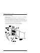
B.2.2 Interfaces
The DLT Mini-Library comes with a differential 68-pin HD D-series connector.
Each drive has a separate bus, with a pair of SCSI-2 connectors, and the library
robotics has a separate bus, with a pair of SCSI-2 connectors. In this
configuration there are six SCSI-2 connectors on the rear panel. In the single-
drive models, two of the six connectors are inactive (DLT2). There is no
requirement that the separate SCSI busses be on the same host.
Both of the drives and the library robotics are separate SCSI devices. Each
requires a unique SCSI address on the bus they are connected to.
It is
recommended to configure the DLT MiniLibrary Tape Drives for
independent SCSI bus interface to achieve maximum transfer performance
for each device.
It is acceptable to daisy-chain Library robotics and one DLT
Tape Drive without impacting system performance.
A terminator of the proper type (differential) must be installed on each unused
connector of each bus, as explained below in the section headed ‘Interface Cable
and Terminator Installation.’ Figure B-5 shows the SCSI cable, connectors and
bus terminator used on the module.
In order to connect the module to a host computer system, the host system must
have at least one SCSI controller and the appropriate driver software. Your
Technical Support representative is available to answer your questions about
installation procedures for specific host systems.
Before cabling the system, see the recommended SCSI cable specifications in
Section B.3, and
Interface Cable and Terminator Installation
in Section B.3.2.