
User`s guide


Appendix B - Installation
EK-TL891-UG .A01 B-7
CAUTION!
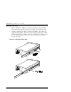
The cooling fan at the rear of the drive must not
be obstructed when the drive is installed in the
rack. It is advisable to allow two inches of
clearance behind the rear panel of the module.
Make certain that when the Module is fully
extended that a force of 20% of the rack weight,
but not more than 57 lb. applied in any direction
but upwards does not cause the rack to
overbalance.
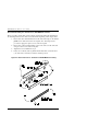
Metric Conversion Bracket Description and Identification:
1. Refer to Figure B-3 to identify and take inventory of the metric conversion
hardware included in your metric rackmount kit.
2. Determine where the module you are installing is going to be located
relative to the top module.
b) If the module you are installing is going to be located on the top of the
stack or the second from the top (unit 1 or 2), the parts which you will
need to install this module are:
2 pieces 968312-101
4 pieces 968313-101
b) If the module you are installing is going to be located third or fourth
from the top (unit 3 and 4), the parts which you will need to install this
module are:
2 pieces 968319-101
4 pieces 968320-101
c) Sort out the appropriate adapters for your application. The part number
is stamped in the middle of the part for identification.
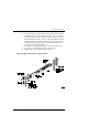
3. Next to each mounting hole in the bracket, numbers are stamped which
correspond to the module number. If you are installing the first module for
example, mount the flat head screws (P/N 213164-108) through the holes
marked #1.