
User`s guide


Appendix B - Installation
EK-TL891-UG .A01 B-3
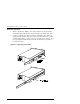
3. Identify and orient the parts of the slides and hardware needed for your
specific rack type. Figure B-2 shows the parts required for Standard
EIA/RETMA rackmounting and Figure B-3 shows the parts for
rackmounting into a Storageworks metric rack.
NOTES:
All of the screws, washers, nutplates and/or
metric conversion brackets required for
rackmounting in either cabinet type are supplied
with the Base Module.
You will need a #2 Phillips
screwdriver and a flathead screwdriver.
The left and right slides are alike, so there is no
risk of confusing the parts on reassembly.
The
front of the cabinet, and front rails
in this text
refers to where the
module face
will be exposed
(typically opposite from the main power source
location). The main power source location thus
becomes the
rear of the cabinet
, and where the
rear rails
exist.
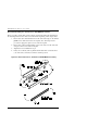
4. Loosely assemble a mounting bracket to each outer slide, using two 10-32
screws with washers and a nutplate for each. Select slots in the mounting
brackets so the length of the assembly equals the distance between the front
and rear rails of the rack.
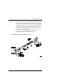
5. Locate the screw holes in the front and rear rails of the cabinet or equipment
rack where the drive is to be installed.
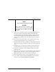
CAUTION!
The cooling fan at the rear of the drive must not
be obstructed when the drive is installed in the
rack. It is advisable to allow two inches of
clearance behind the rear panel of the module.
6. From this point, the instructions vary depending on cabinet type, and you
should proceed as follows:
• EIA/RETMA Cabinet Rackmounting - Refer to Section B.1.1.
• StorageWorks Metric Rackmounting - Refer to Section B.1.2.