
User`s guide


Chapter 2. Operation
EK–TL891–UG. A01 2–-7
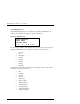
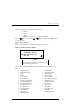
The fourth line is a map of the magazine with numbers from 0 to 9 representing
the cartridge slots. The numbers which are present on this line indicate that a
cartridge is present in the corresponding slot of the magazine. An underline
means that there is no cartridge present in that slot. In Figure 2-5, the cartridges
from slots 3 and 5 are not in the magazine, but are in drives 0 and 1.
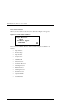
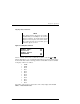
2.3.4 Fault Screen
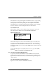
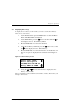
When a fault is detected, a screen similar to Figure 2-6 appears. At the same
time, either the Drive Fault or the Loader Fault LED is illuminated.
Figure 2-6 Fault Screen
The first line in Figure 2-6 shows a numerical fault symptom code (FSC). The
second line shows a brief description of the error, in place of the words ‘Error
Description.’ The third and fourth lines will contain a one- or two-line message
describing the initial error recovery procedure (ERP) in place of the words shown
in the figure.
A list of the fault symptom codes (FSC) and error recovery procedures (ERP)
appears in
Chapter 5 - Diagnostics and Troubleshooting
.
2.4 Selecting Control Panel Display Modes
As previously described, the POST Screens, the Initialization Screen and the
Default Screen appear without operator or host intervention. The Fault Screens
appear whenever a fault occurs. The screens which follow appear in response to
operator actions.
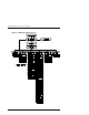
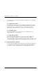
2.4.1 The Mini-Library Menu Structure
Figure 2-7 shows the structure of the MiniLibrary menus.
Fault Code: XXXX
Error Description
ERP line 1
ERP line 2