
User`s guide


Chapter 2. Operation
EK–TL891–UG. A01 2–-5
2.3 Display Messages
The display on the control panel is capable of displaying four lines of 20
characters each, to allow the use of easy-to-understand messages. Many of these
messages and their functions are described in this chapter. Those displays that
are described in other chapters are cross-referenced here as well.
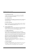
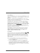
2.3.1 Power-On Self Test Screen
When power is first applied to the module, a series of power-on self test (POST)
diagnostics are performed. During POST execution, the model number of the
module, the current date and time, the firmware revision, and the status or result
of the test in progress are displayed on the control panel as shown in figure 2-3.
Figure 2-3 POST Screen
NOTE
xx.xx represents decimal placeholders for the
current firmware revision level.
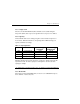
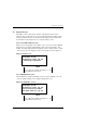
2.3.2 Initialization Screens
After the POST is completed, the library robotics system is initialized. A series
of screens similar to Figure 2-4 is displayed during this process.
Figure 2-4 Initialization Screen
NOTE
xx.xx represents decimal placeholders for the
current firmware revision level.
DIGITAL TL89x
Firmware Level xx.xx
Checking Hardware
DIGITAL TL89x
Firmware Level xx.xx
Initializing Loader
26-Feb-19xx 15:35:59