
User`s guide


DLT MiniLibrary (TL891) - User’s Guide
1–2 EK–TL891–UG. A01
1.2 Features
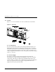
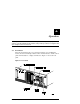
Figures 1-1, 1-2 and 1-3 identify some of the external features of the TL891.
Figure 1-1 Front View
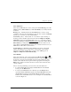
1.2.1 Control Panel
The control panel features a 4-line by 20-character backlit LCD display, four
LED indicators and four buttons. The buttons enable the operator to navigate
through the menu structure to select and display operating modes, device status,
diagnostic and maintenance functions, device history and error statistics, and
system configuration. The functions of the control panel are described in detail in
Chapter 2 - Operation.
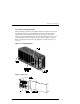
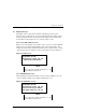
1.2.2 Power Supply
The AC Power switch is located on the front panel of the module. The
autoranging power supply will adjust automatically to either of two operating
voltage ranges. The ranges are 100-120 VAC and 200-240 VAC. The power
supply is capable of operating at 50 or 60 Hz without requiring any modification.
AC power is supplied to the power supply by a single cable which can be
plugged into any properly grounded outlet.