Hardware Reference Guide HP Compaq t5720/t5725 Thin Client Document Part Number: 405356-002 July 2006 This book provides basic hardware information for this series of thin clients.
© Copyright 2005, 2006 Hewlett-Packard Development Company, L.P. The information contained herein is subject to change without notice. Microsoft, MS-DOS, Windows, and Windows NT are trademarks of Microsoft Corporation in the U.S. and other countries. The only warranties for HP products and services are set forth in the express warranty statements accompanying such products and services. Nothing herein should be construed as constituting an additional warranty.
Contents 1 Product features Standard features . . . . . . . . . . . . . . . . . . . . . . . . . . . . . . . . . . . . . . . . . . . . . . . . . . . . . . Front panel components . . . . . . . . . . . . . . . . . . . . . . . . . . . . . . . . . . . . . . . . . . . . . . . . Rear panel components . . . . . . . . . . . . . . . . . . . . . . . . . . . . . . . . . . . . . . . . . . . . . . . . . System board components. . . . . . . . . . . . . . . . . . . . . . . . . . . . . . . . . . . . . . . . . . . . . . .
Contents C Mounting the thin client HP Quick Release . . . . . . . . . . . . . . . . . . . . . . . . . . . . . . . . . . . . . . . . . . . . . . . . . . . . . C–1 Supported mounting options. . . . . . . . . . . . . . . . . . . . . . . . . . . . . . . . . . . . . . . . . . C–5 Non-supported mounting option . . . . . . . . . . . . . . . . . . . . . . . . . . . . . . . . . . . . . . . C–8 D Electrostatic discharge Preventing electrostatic damage . . . . . . . . . . . . . . . . . . . . . . . . . . . . . . . .
1 Product features Standard features HP Compaq t5720/t5725 thin clients are terminals that connect to a Microsoft server with Citrix MetaFrame software running atop the server operating system. HP has partnered with Altiris to manage HP Compaq thin clients. Altiris Deployment Solution is a leading-edge tool to help with quick deployment and for on-going management of the thin clients in your organization. Each HP Compaq thin client is recognized by the Altiris Deployment Solution as a supported device.
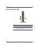
Product features Front panel components Front panel components 1 Power button 3 Flash activity LED 2 Power LED 4 USB ports (2) * For more information, refer to the model-specific QuickSpecs at http://h18004.www1.hp.com/products/quickspecs/QuickSpecs_A rchives/QuickSpecs_Archives.html. 1-2 www.hp.
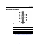
Product features Rear panel components Rear panel components 1 Cable lock slots 6 Universal Serial Bus (USB) connectors (4) 2 Ethernet RJ-45 connector 7 Line-in audio connector (microphone) 3 Line-out audio (headphone) connector 8 Monitor connector 4 PS/2 connectors (2) 9 Serial connector 5 Parallel connector : Power connector * For more information, refer to the model-specific QuickSpecs at http://h18004.www1.hp.com/products/quickspecs/QuickSpecs_A rchives/QuickSpecs_Archives.html.
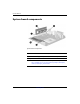
Product features System board components System board components 1 PCI riser slot 4 SODIMM memory 2 PCI riser card (optional) 5 Flash memory 3 Speaker connector * For more information, refer to the model-specific QuickSpecs at http://h18004.www1.hp.com/products/quickspecs/QuickSpecs_ Archives/QuickSpecs_Archives.html. 1-4 www.hp.
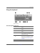
Product features Using the keyboard Keyboard features Enhanced keyboard components 1 Caps Lock key Activates/deactivates the Caps Lock feature. 2 Scroll Lock key Activates/deactivates the Scroll Lock feature. 3 Num Lock key Activates/deactivates the Num Lock feature. 4 Ctrl key Use in combination with another key; its function depends on the application software you are using. 5 Windows Logo Key1 Opens the Start menu in Microsoft Windows.
Product features Enhanced keyboard components (Continued) 6 Alt key Use in combination with another key; its function depends on the application software you are using. 7 Application key1 Opens (like the right mouse button) pop-up menus in a Microsoft Office application. May perform other functions in other software applications. 8 Editing keys Includes the following: Insert, Home, Page Up, Delete, End, and Page Down. Hold down Ctrl and Alt while pressing Delete to restart the thin client.
Product features Additional function keys The following key combinations also work on the HP Compaq t5720/t5725 thin client: Alt + Esc Cycles through minimized applications. Alt + Tab Cycles through open applications. Alt + Shift + Tab Switches to the previous session. Special mouse functions Most software applications support the use of a mouse. The functions assigned to each mouse button depend on the software applications you are using.
Product features 1-8 www.hp.
2 Hardware upgrades General hardware installation sequence To ensure the proper installation of any thin client hardware option: 1. Back up any data, if necessary. 2. If the thin client is powered on: a. Shut the unit down. b. Turn the unit and any other attached devices off. c. Disconnect the power cord from the wall outlet. d. Disconnect any external devices or cables.
Hardware upgrades 3. Remove the chassis cover. For more information, see “Removing and replacing the chassis cover” on page 2-3. 4. If necessary, remove any hardware that you will replace. 5. Install or replace equipment. For removal and replacement procedures, see the following sections: ❏ Flash memory upgrade on page 2-4 ❏ SODIMM upgrade on page 2-6 ❏ PCI Expansion Module on page 2-7 ❏ Internal battery on page 2-10 ✎ Option kits include more detailed installation instructions. 6.
Hardware upgrades Removing and replacing the chassis cover To install internal hardware, you must remove the chassis cover as shown in the following procedures. Å WARNING: Before removing the chassis cover, ensure that the thin client is turned off and the power cord is disconnected from the electrical outlet. 1. Remove the two screws that secure the cover to the chassis 1. 2. Slide the cover about 1/2-inch toward the back of the unit, and then lift the cover off the chassis 2. 3.
Hardware upgrades Installing thin client options The t5720/t5725 thin client offers several options, including flash memory, SODIMMs, and security hardware. For more information about security hardware, see Appendix B, “Security provisions”. To view and order available options, visit the HP Web site at http://h18004.www1.hp.com/products/thinclients/options /index.html. The following sections contain general installation instructions for some of the available options.
Hardware upgrades 3. Verify the location of the round opening on the flash memory card and align the opening with the plastic stem on the system board. 4. Insert the new flash memory with the connectors facing down as shown in the following illustration. Installing flash memory 5. Complete steps 6 through 8 of the “General hardware installation sequence” on page 2-1. 6. Install the thin client software.
Hardware upgrades SODIMM upgrade Use the following procedure to upgrade or replace the SODIMM module. Ä CAUTION: If necessary, back up any data before continuing the installation. addition to following these instructions, follow the detailed ✎ Ininstructions that accompany the module. 1. Complete steps 1 through 4 of the “General hardware installation sequence” on page 2-1. 2. Remove the existing SODIMM module. 3.
Hardware upgrades PCI Expansion Module can order the PCI Expansion Module kit at ✎ You http://h18004.www1.hp.com/products/thinclients/ options/index.html. Installation of a PCI Expansion Module requires that you replace the chassis cover with a PCI Expansion Module chassis cover. To install a PCI Expansion Module, follow the instructions included in the option kit.
Hardware upgrades 2. Install the PCI riser card in the PCI expansion slot on the system board, as shown in the following illustration. Installing PCI riser card 3. Connect the speaker cable from the PCI Expansion Module chassis cover to the system board. The speaker is installed in the PCI Expansion Module chassis cover. Connecting the speaker 2-8 www.hp.
Hardware upgrades 4. Install a PCI card 1 into the PCI riser card as shown in the following illustration. 5. Install the optional PCI Expansion Module chassis cover 2. 6. Secure the optional PCI Expansion Module chassis cover with the two chassis screws 3. Installing a PCI card and PCI Expansion Module chassis cover 7. Complete steps 6 through 10 of the “General hardware installation sequence” on page 2-1. To remove the PCI Expansion Module, reverse the previous procedure. Hardware Reference Guide www.
Hardware upgrades Internal battery 1. Complete steps 1 through 4 of the “General hardware installation sequence” on page 2-1. 2. Locate the battery on the system board. 3. Pull back on the clip 1 that is holding the battery in place, and then remove the battery 2. 4. Insert the new battery and position the clip back into place. Removing and replacing the internal battery 5. Complete steps 6 through 10 of the “General hardware installation sequence” on page 2-1.
A Specifications HP Compaq t5720/t5725 Thin Client Dimensions Height Width Depth 9.85 in 2.59 in 8.09 in 250.18 mm 65.71 mm 205.55 mm Approximate Weight 3.7 lb 1.7 kg 50° to 104° F 10° to 40° C -22° to 140° F -30° to 60° C Temperature Range (fanless design)* Operating** (max. rate of change is 10° C per hour or 18° F per hour) Nonoperating (max. rate of change is 20° C per hour or 36° F per hour) *Specifications are at sea level with altitude derating of 1° C/300m (1.
Specifications HP Compaq t5720/t5725 Thin Client (cont) Relative Humidity (non-condensing) Operating 10–90% 10–90% 5–95% 5–95% 10,000 ft 3048 m 30,000 ft 9144 m Operating Voltage Range Rated Line Frequency 100–240 VAC 50–60 Hz 100–240 VAC 50–60 Hz Power Output (maximum) 40 W 40 W Rated Output Current (maximum) 3.3 A 3.3 A 136.4 BTU/hr 2.94 BTU/hr 34.4 kg-cal/hr 0.74 kg-cal/hr (max. wet bulb temperature is 28° C or 84.2° F) Nonoperating (max. wet bulb temperature is 38.7° C or 101.
B Security provisions Securing the thin client The HP Compaq t5720/t5725 thin client is designed to accept a security cable lock. This cable lock prevents unauthorized removal of the thin client. To order this option, visit the HP web site at http://h18004.www1.hp.com/products/thinclients/ options/index.html. 1. Locate the cable lock slot 1 on the back panel. There are two slots available. 2. Insert the cable lock 2 and use the key 3 to lock it. Securing the thin client Hardware Reference Guide www.hp.
Security provisions B-2 www.hp.
C Mounting the thin client HP Quick Release The HP Compaq t5720/t5725 thin client incorporates four mounting points on each side of the unit. These mounting points follow the VESA (Video Electronics Standards Association) standard, which provides industry-standard mounting interfaces for Flat Displays (FDs), such as flat panel monitors, flat displays, and flat TVs. The HP Quick Release connects to the VESA-standard mounting points, allowing you to mount the thin client in a variety of orientations.
Mounting the thin client To use the HP Quick Release with a VESA-configured thin client: 1. Using four screws included in the mounting device kit, attach one side of the HP Quick Release to the thin client as shown in the following illustration. Connecting the HP Quick Release to the thin client C-2 www.hp.
Mounting the thin client 2. Using four screws included in the mounting device kit, attach the other side of the HP Quick Release to the device to which you will mount the thin client. Make sure the release lever points upward. Connecting the HP Quick Release to another device Hardware Reference Guide www.hp.
Mounting the thin client 3. Slide the side of the mounting device attached to the thin client 1 over the other side of the mounting device 2 on the device on which you want to mount the thin client. An audible ‘click’ indicates a secure connection. Connecting the thin client attached, the HP Quick Release automatically locks in ✎ When position. You only need to slide the lever to one side to remove the thin client.
Mounting the thin client Supported mounting options The following illustrations demonstrate some of the supported and not supported mounting options for the mounting bracket. ■ You can mount a thin client between a flat panel monitor and the wall. Thin client mounted with flat panel on wall Hardware Reference Guide www.hp.
Mounting the thin client ■ You can mount the thin client on the back of a flat panel monitor stand. Thin client mounted on back of monitor stand ■ You can mount the thin client on a wall. Thin client mounted on wall C-6 www.hp.
Mounting the thin client ■ You can mount the thin client under a desk. Thin client mounted under desk Hardware Reference Guide www.hp.
Mounting the thin client Non-supported mounting option Ä CAUTION: Mounting a thin client in an non-supported manner could result in failure of the HP Quick Release and damage to the thin client and/or other equipment. Do not mount the thin client on a flat panel monitor stand, between the panel and the stand. Unsupported mounting position - thin client between stand and monitor C-8 www.hp.
D Electrostatic discharge A discharge of static electricity from a finger or other conductor may damage system boards or other static-sensitive devices. This type of damage may reduce the life expectancy of the device. Preventing electrostatic damage To prevent electrostatic damage, observe the following precautions: Hardware Reference Guide ■ Avoid hand contact by transporting and storing products in static-safe containers.
Electrostatic discharge Grounding methods There are several methods for grounding. Use one or more of the following methods when handling or installing electrostatic-sensitive parts: ■ Use a wrist strap connected by a ground cord to a grounded Thin Client chassis. Wrist straps are flexible straps with a minimum of 1 megohm +/- 10 percent resistance in the ground cords. To provide proper grounding, wear the strap snug against the skin. ■ Use heelstraps, toestraps, or bootstraps at standing workstations.
E Thin client operation Routine thin client care Use the following information to properly care for your thin client: Hardware Reference Guide ■ Operate the thin client on a sturdy, level surface. Leave a 1-inch (2.5-cm) clearance around the air vents to permit the required airflow. ■ Never operate the thin client with the outside panel removed. ■ Never restrict the airflow into the thin client by blocking the vents or air intake.
Thin client operation Supported orientations HP supports the following orientations for the thin client. Ä CAUTION: You must adhere to HP-supported orientations to ensure your thin clients function properly. ■ You can stand thin clients vertically. Vertical orientation E-2 www.hp.
Thin client operation ■ You can lay thin clients horizontally. Horizontal orientation ■ You can lay thin clients under a monitor stand with a one-inch clearance above the unit. Under monitor stand Hardware Reference Guide www.hp.
Thin client operation Non-supported orientations HP does not support the following orientations for the thin client. Ä CAUTION: Non-supported placement of thin clients could result in operation failure and/or damage to the devices. Ä CAUTION: Thin clients require proper ventilation to maintain operating temperature. ■ Do not put a monitor directly on top of a thin client. Do not put a monitor on top of the thin client E-4 www.hp.
Thin client operation ■ Do not horizontally stack thin clients. Thin clients require proper ventilation to maintain operating temperatures. Do not stack thin clients ■ Do not put thin clients in drawers or other sealed enclosures. Thin clients require proper ventilation to maintain operating temperatures. Do not put thin clients in drawers or other sealed enclosures Hardware Reference Guide www.hp.
Thin client operation ■ Do not place materials on thin clients that block the vents. Thin clients require proper ventilation to maintain operating temperatures. Do not block the vents of the thin client ■ Do not position the thin client vertically without using the stand. Do not position the thin client vertically without using the stand E-6 www.hp.
F Shipping information Shipping preparation Follow these suggestions when preparing to ship the thin client: 1. Turn off the thin client and external devices. 2. Disconnect the power cord from the electrical outlet, then from the thin client. 3. Disconnect the system components and external devices from their power sources, then from the thin client. 4. If you have upgraded the SODIMM, remove it and replace the original SODIMM that came with the unit. 5.
Shipping information Important service repair information In all cases, remove and safeguard all external options before returning the thin client to HP for repair or exchange. In countries that support customer mail-in repair by returning the same unit to the customer, HP makes every effort to return the repaired unit with the same internal memory and flash modules that were sent.
Index A Altiris Deployment Solution 1–1 altitude specifications A–2 B flash memory 2–4 installing 2–4 location 1–4 front panel components 1–2 battery 2–10 G C grounding methods D–2 cable lock installing B–1 slot location 1–3 cautions backing up data 2–4 static electricity 2–1 chassis cover removing 2–3 components front panel 1–2 keyboard 1–5 mouse 1–7 rear panel 1–3 D dimensions A–1 diskette drive 2–10 downloads Web site 2–2 E electrostatic discharge D–1 ethernet connector 1–3 F Flash activity LED
Index K keyboard 1–5 connector 1–3 function keys 1–7 layout 1–5 Windows logo key 1–6 L line-in audio connector 1–3 line-out audio connector 1–3 M memory installing 2–6 socket location 1–4 microphone connector 1–3 mounting options on back of monitor stand C–6 on wall C–6 under desk C–7 with flat panel on wall C–5 mouse 1–7 mouse connector 1–3 N non-supported orientations in a drawer E–5 monitor on top E–4 stack horizontally E–5 vertical without stand E–6 with blocked vents E–6 O options installing 2–1,
Index supported orientations E–2 horizontal E–3 under monitor stand E–3 vertical E–2 system board components 1–4 T temperature specifications A–1 thin client features 1–1 U unsupported mounting option between stand and monitor C–8 USB port location 1–2, 1–3 W warnings electric shock 2–1 fire 2–1 Web sites Altiris 1–1 downloads 2–2 options 2–4, 2–7, B–1, C–1 QuickSpecs 1–2, 1–3, 1–4 software installation instructions 2–5 thin client features 1–1 USB drive options 2–10 weight A–1 Windows Logo Key 1–5 Har
Index Index-4 www.hp.